
This tutorial is also available in French
➔

Fuel pressure regulator change on Defender Td5
Vehicle ➔ Defender 110 Td5 year 2002
Difficulty ➔ Medium
Time ➔ 3 hours
Summary
Advertisement
Advertisement

Recommendations

This tutorial concerns the replacement of the fuel pressure regulator sold by Land Rover spare parts dealers. However, in most cases, only the small capsule of the regulator is faulty and it is enough to simply change it to eliminate the fuel leak. This trick allows you to repair your Defender for 4 times cheaper. If you want to know more about this matter, we have done a tutorial that deals with the refurbishment of the fuel pressure regulator
(➔ see the tutorial).

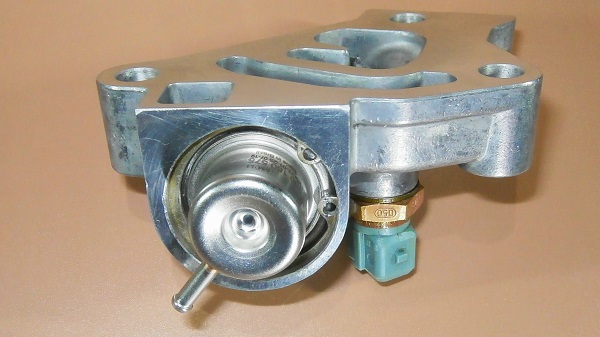
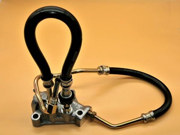
There are 2 types of fuel pressure regulators for the Defender Td5 :
• The ref LR016319 is fitted on Defenders up to year 2001 (serial number 1A622423).
• The ref LR016318 is fitted on Defenders from year 2002 (serial number 2A622424).
This tutorial concerns reference LR016318.
• The ref LR016319 is fitted on Defenders up to year 2001 (serial number 1A622423).
• The ref LR016318 is fitted on Defenders from year 2002 (serial number 2A622424).
This tutorial concerns reference LR016318.
The easiest way to determine which regulator is fitted to your Defender is as follows :
• The ref LR016319 has 2 fuel hoses.
• The ref LR016318 has 3 fuel hoses.
If you see a hose going from the regulator to the front of the cylinder head, it is a 3-hose regulator (LR016318).
• The ref LR016319 has 2 fuel hoses.
• The ref LR016318 has 3 fuel hoses.
If you see a hose going from the regulator to the front of the cylinder head, it is a 3-hose regulator (LR016318).
The fuel pressure regulator is traditionally sold with its hoses (LR016318) but some dealers now sell it without its hoses (LR016318GR). This option is interesting because when the regulator starts to leak, the hoses are often still in good condition and there is no need to change them. This reduces the bill a little.
Changing the fuel pressure regulator causes air to enter the fuel system. It is therefore essential to bleed the fuel system before starting the engine. This operation is very simple (see Op 38).
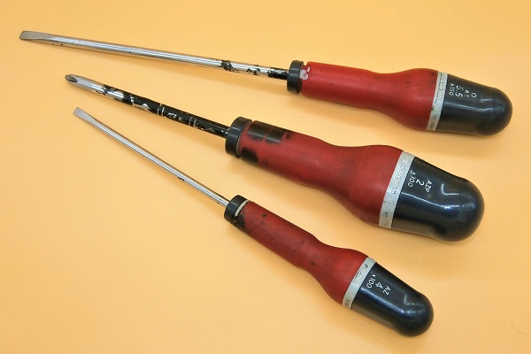
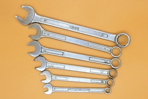
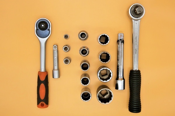
Required Tools
Sponsored links by

Spare Parts
Our Partner

Packaging :
•
All the above parts are sold individually.
• LR016318 : The fuel pressure regulator is sometimes supplied with its gasket MSX000010 (check before placing the order).
• LR016318 : The fuel pressure regulator is sometimes supplied with its gasket MSX000010 (check before placing the order).
Advertisement
Preliminary actions
Op 01
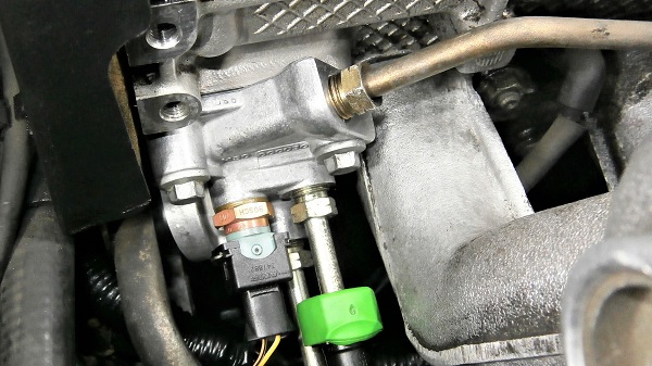
Locate the fuel pressure regulator.


Op 02
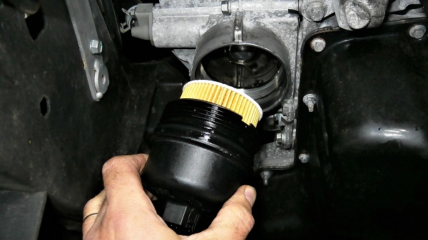
Remove the acoustic cover (➔ see the tutorial ''Engine oil change on Defender Td5'' Op 05 to 07).
Remove the fuel pressure regulator
Op 03
Unscrew the 2 rear engine lifting bracket fixing bolts. Use the 10 mm socket.


Op 04
Remove the rear engine lifting bracket.
Removing this bracket is not essential but it allows better access to the fuel pressure regulator.


Op 05
Disconnect the connector from the temperature sensor. Press the locking clip and pull by hand.


Op 06
Unscrew the locking nut of the upper fuel hose. Use the 14 mm spanner.
Release the hose from the fuel pressure regulator. Pull by hand.
Always seal the hoses with rags to prevent any impurities from entering the fuel system.


Op 07
Disconnect the fuel supply hose from the fuel pressure regulator :
•
Move the green cover away.
•
Press the 2 locking tabs with your fingers.
•
Detach the fuel supply hose. Pull by hand.
•
Recover the green cover.


Op 08
Unscrew the locking nut of the rigid fuel pipe. Use the 14 mm spanner.
Remove the rigid fuel pipe. Pull by hand.


Op 09
Disconnect the fuel cooler hose :
•
Slide the black collar towards the hose. Use a flathead screwdriver.
•
Detach the hose. Pull by hand.
This operation is delicate because the hose connector is hidden behind the fuel cooler.
The movements must be broken down : first slide the black collar without pulling on the hose (this releases the locking mechanism) and when the mechanism is unlocked, pull on the hose to disconnect it.


Op 10
Unscrew the locking nut of the fuel cooler hose. Use the 14 mm spanner.
Remove the hose. Pull by hand.
Be careful not to damage the temperature sensor when unscrewing the nut.
Removing this hose is not essential before the fuel pressure regulator removal. However, it greatly facilitates access to the bottom fixing bolt.


Op 11
Remove the 3 fixing bolts of the fuel pressure regulator. Use the 10 mm socket.
Seen from above, the bottom bolt is completely invisible. You have to feel your way to place the socket on the bolt head and unscrew it.


Op 12
Remove the fuel pressure regulator and its gasket.


Op 13
Remove the fuel strainer O-ring. Detach it with your fingernail or use a small flathead screwdriver.


Op 14
Remove the fuel strainer from the cylinder head. Use a small flathead screwdriver and pull by hand.
The fuel strainer is simply slipped into the cylinder head. Just slide it with the screwdriver to remove it.
The fuel strainer is very fragile. Do not damage it with the screwdriver.


Advertisement
Prepare the new regulator
Op 15
Unscrew the temperature sensor from the fuel pressure regulator. Use the 19 mm spanner.


Op 16
Remove the seal from the temperature sensor. Pull by hand.
Discard the seal.


Op 17
Take the new fuel pressure regulator (LR016318).

Op 18
Unscrew the locking nut of the upper fuel hose. Use the 14 mm spanner.
Remove the hose. Pull by hand.
To simplify the task, we will not use this new upper hose. We will simply connect the old upper fuel hose to the new fuel pressure regulator.


Op 19
Disconnect the fuel cooler hose from the rigid fuel pipe.
Slide the black collar towards the hose and then pull on the hose to disconnect it.


Op 20
Unscrew the locking nut of the rigid fuel pipe. Use the 14 mm spanner.
Remove the rigid fuel pipe. Pull by hand.
Removing the rigid fuel pipe is not essential but it facilitates access to the fuel pressure regulator during reassembly. Particularly when tightening the 3 fixing bolts to the torque.


Op 21
Unscrew the locking nut of the fuel cooler hose. Use the 14 mm spanner.
Remove the hose. Pull by hand.
Removing the fuel cooler hose is not essential but it facilitates access to the fuel pressure regulator during reassembly. Particularly when tightening the 3 fixing bolts to the torque.


Op 22
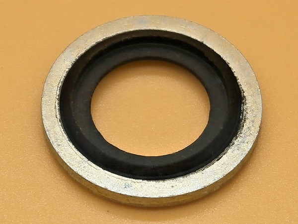
Fit a new seal (ERR6192) on the temperature sensor. Push by hand.


Op 23
Screw the temperature sensor onto the fuel pressure regulator. Use the 19 mm spanner.
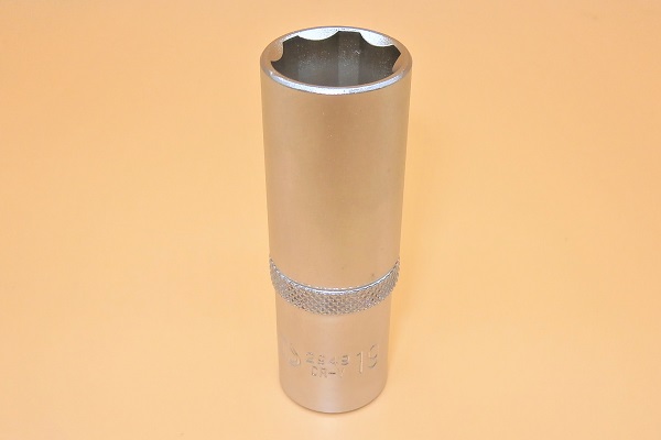
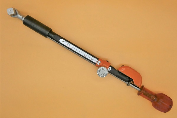
Tighten the temperature sensor to a torque of 14 mN. Use the 19 mm deep socket and the torque wrench.


Fit the fuel pressure regulator
Op 24
Fit the fuel strainer in the cylinder head. Push by hand.
Make sure the strainer stays in place and does not fall out.


Op 25
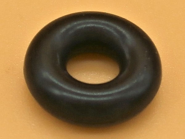
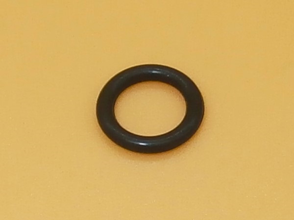
Fit the fuel strainer O-ring (ERR6761). Push by hand.
Put a few drops of fuel on the O'ring before installation.


Op 26
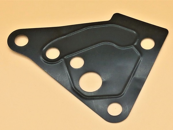
Fit the new gasket (MSX000010) on the fuel pressure regulator.
Make sure the gasket is in the correct position (2nd photo). The gasket openings must match the regulator openings.
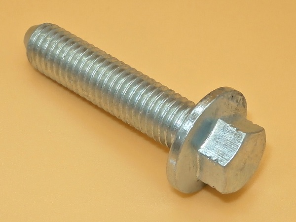
Use 2 of the 3 regulator fixing bolts (FS108357) to guide the gasket.


Op 27
Fit the fuel pressure regulator on the cylinder head.


Op 28
Screw in the 3 fixing bolts. Use the 10 mm socket.
Tighten the 3 bolts to a torque of 25 mN. Use the torque wrench.


Op 29
Engage the fuel cooler hose into the fuel pressure regulator. Push by hand.
Tighten the locking nut. Use the 14 mm spanner.
Put a few drops of fuel on the O'ring before engaging the hose.


Op 30
Connect the hose to the fuel cooler. Push by hand.


Op 31
Engage the rigid fuel pipe into the fuel pressure regulator. Push by hand.
Tighten the locking nut. Use the 14 mm spanner.
Put a few drops of fuel on the O'ring before engaging the pipe.


Op 32
Connect the fuel supply hose to the rigid fuel pipe of the fuel pressure regulator :
•
Engage the green cover on the rigid fuel pipe. Push by hand.
•
Connect the hose. Push by hand.
•
Slide the green cover onto the connector. Push by hand.


Op 33
Fit the new O-ring (STC4509) on the upper fuel hose. Push by hand.


Op 34
Fit the new O-ring (STC4509) on the upper fuel hose. Push by hand.
Put a few drops of fuel on the O'ring before installation.

Op 35
Engage the upper fuel hose into the fuel pressure regulator. Push by hand.
Tighten the locking nut. Use the 14 mm spanner.


Op 36
Plug the connector onto the temperature sensor. Push by hand.
Make sure there is no fuel in the connector. If so, clean it properly.
There is a cutout on the connector (1st photo) and a keyway on the temperature sensor. It is impossible to plug it in backwards.


Op 37
Fit the rear engine lifting bracket.
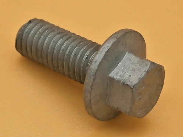
Screw in the 2 fixing bolts (FS108207L). Use the 10 mm socket.


Advertisement
Bleed the fuel system
Op 38
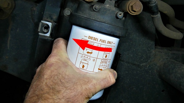
Bleed the fuel system (➔ see the tutorial ''Fuel filter change on Defender Td5'' Op 17).
Final actions
Op 39
Start the engine.
Check that there are no leaks at the fuel pressure regulator.

Op 40
Take a road test and check again that there are no fuel leaks.
Op 41
Fit the acoustic cover (➔ see the tutorial ''Engine oil change on Defender Td5'' Op 44 to 46).
The End