
This tutorial is also available in French
➔

Clutch master cylinder change on Defender Td5
Vehicle ➔ Defender 110 Td5 2002
Difficulty ➔ Medium

Time ➔ 4 hours
Summary
Advertisement
Advertisement

Recommendations

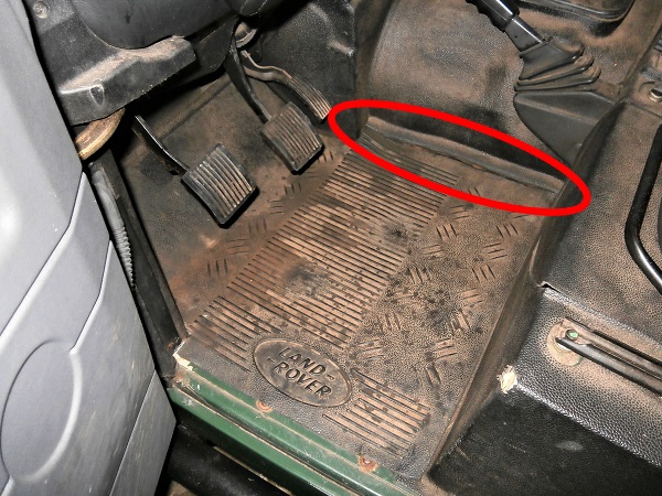
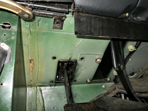
You have a small oil stain on the rubber floor mat under the clutch pedal ?
The clutch master cylinder is almost dead. It needs to be changed soon. Indeed, the clutch hydraulic system will gradually empty of its fluid and you will soon no longer be able to disengage the clutch. The Defender will then be immobilized.
The clutch master cylinder is almost dead. It needs to be changed soon. Indeed, the clutch hydraulic system will gradually empty of its fluid and you will soon no longer be able to disengage the clutch. The Defender will then be immobilized.

This tutorial describes the traditional method for changing the clutch master cylinder. This method involves completely removing the pedal + master cylinder assembly from the vehicle. The master cylinder can then be changed easily on a workbench. Some Land Rover enthusiasts prefer to use another method. This consists of leaving the pedal in place and changing the master cylinder directly on the Defender. This method is probably faster but it requires the hands of a midwife.
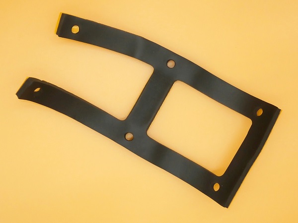
You will see that removing the clutch pedal bracket from the engine compartment is very complicated. Although care is taken to move the brake pedal bracket beforehand, there is very little space and every millimeter counts.
Used brake fluid is a hazardous product. It must not be thrown into the environment, into the sanitation system, or into household waste. Put the used brake fluid in a container and take the container to the recycling center.
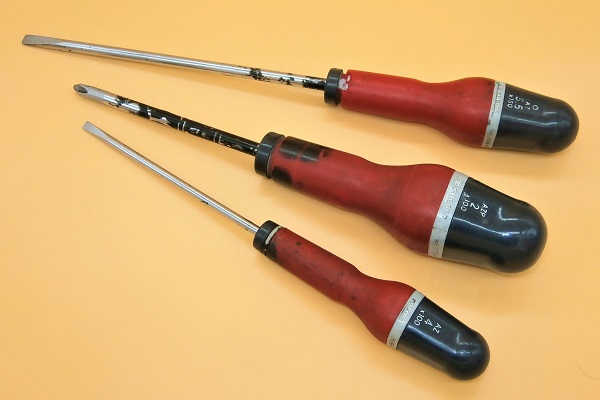
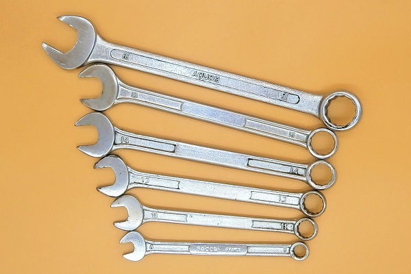
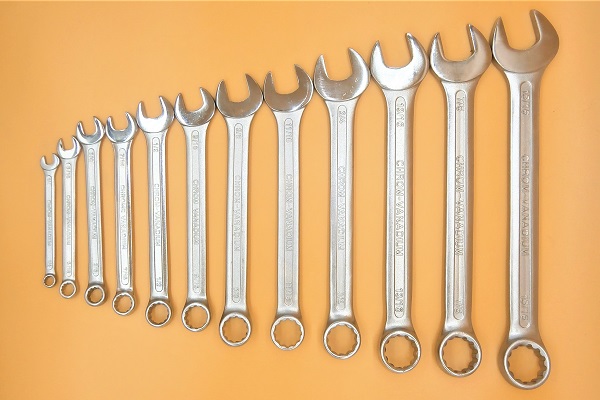
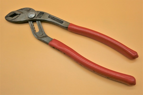
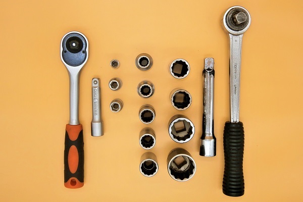
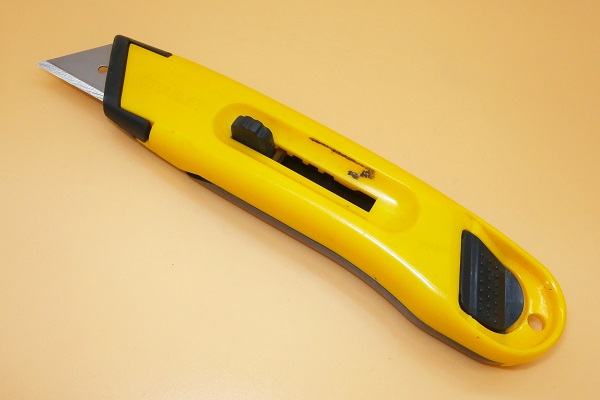
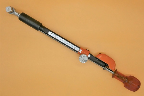
Required Tools
Sponsored links by

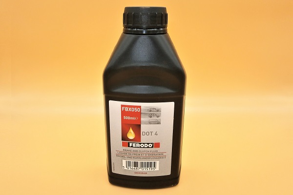
Spare Parts
Sponsored links by

Packaging :
•
All the above parts are sold individually.
Advertisement
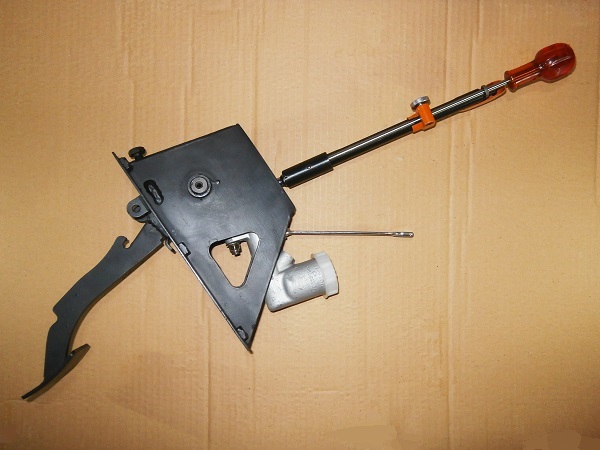
Remove the pedal + master cylinder assembly
Op 01
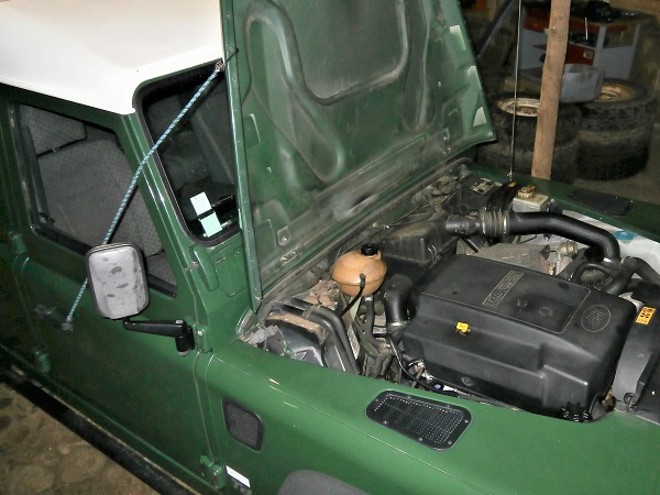
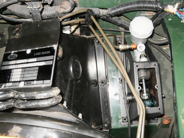
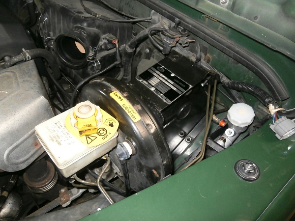
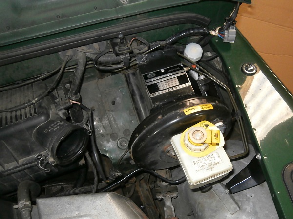
Open the bonnet and lean it against the windscreen.
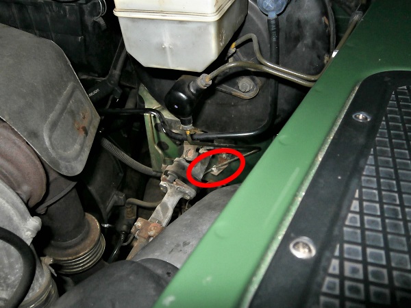
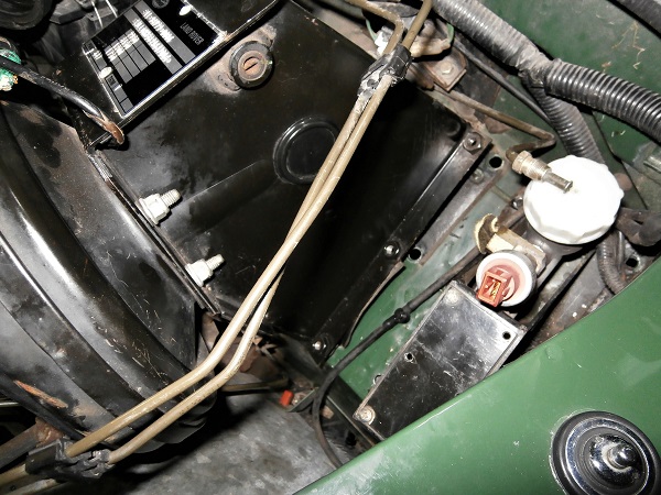
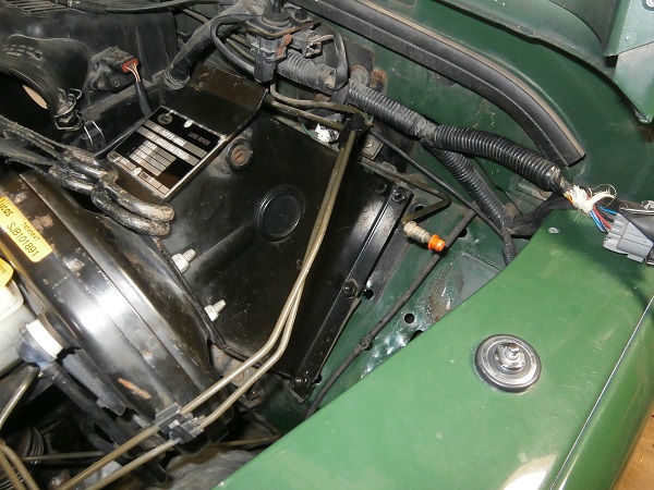
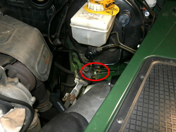
The bonnet must be fully open to access the clutch master cylinder. The master cylinder is located against the bulkhead.
Secure the bonnet with a strap.
If you are working outside, it is best to completely remove the bonnet and thus avoid receiving it on your head at the slightest gust of wind.
Op 02
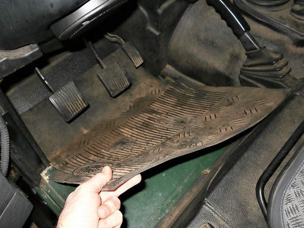
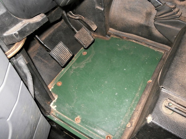
Remove the driver's side rubber floor mat.
On our Defender, the mat has been cut at the gearbox tunnel (1st photo). This makes it much easier to remove during cleaning.
Removing the mat is not essential but it makes it easier to remove the trim during the following operations.
Op 03
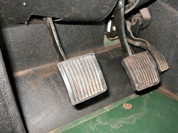
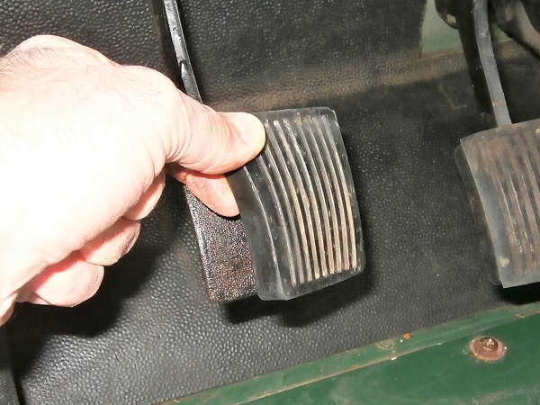
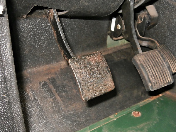
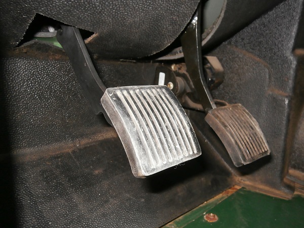
Remove the clutch pedal rubber. Pull by hand.
Op 04
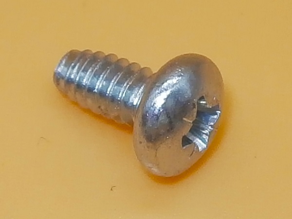
Unscrew courtesy light switch fixing screw. Use the Phillips screwdriver.
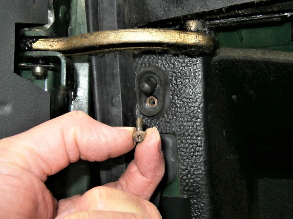
Op 05
Remove courtesy light switch. Pull by hand.
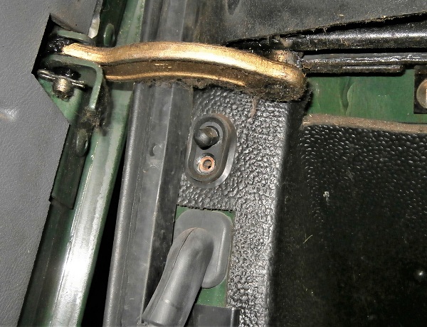
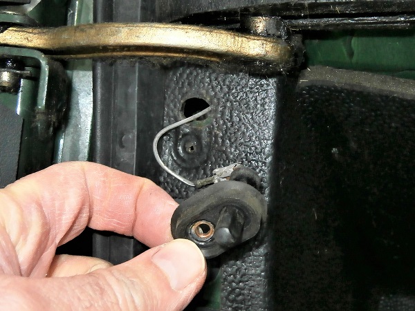
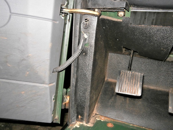
Op 06
Disconnect the courtesy light switch. Pull by hand.
Do not let the cable go back into the body.
Op 07
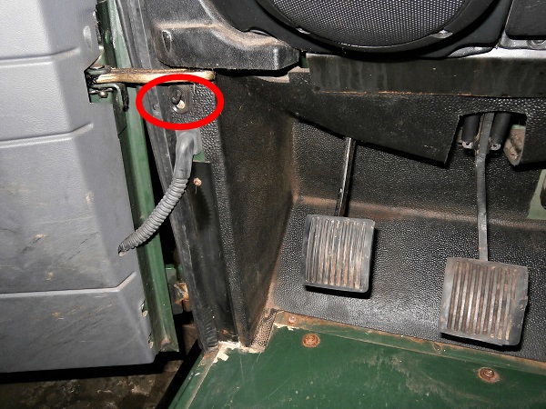
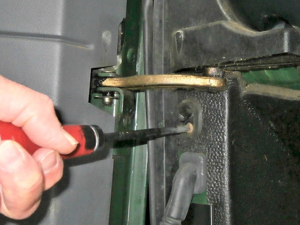
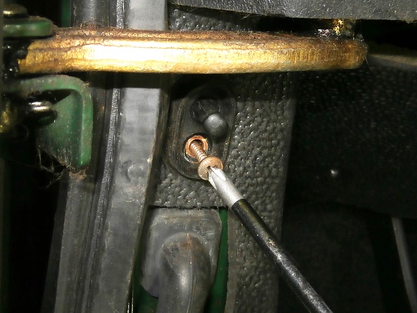
Unscrew the 2 trim fixing screws located to the left of the clutch pedal. Use the Phillips screwdriver.
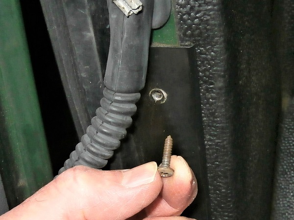
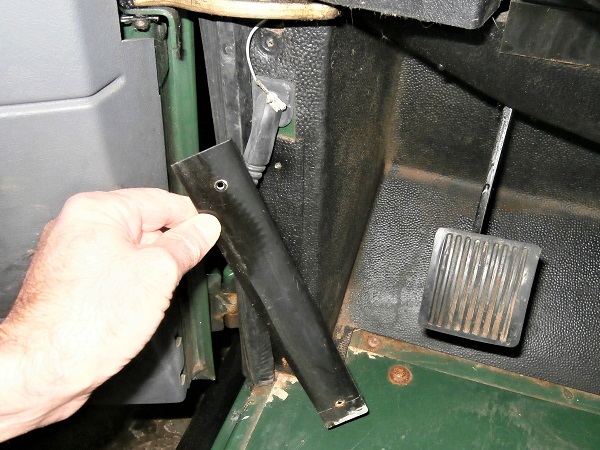
Op 08
Remove trim retainer. Pull by hand.
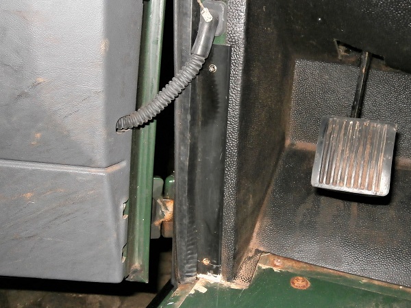
Op 09
Remove the door seal only in the lower part. Pull by hand.
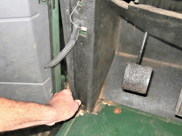
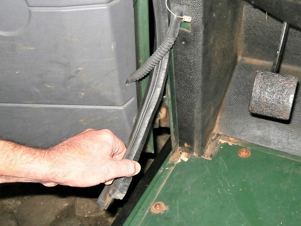
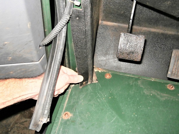
Op 10
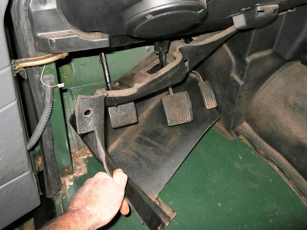
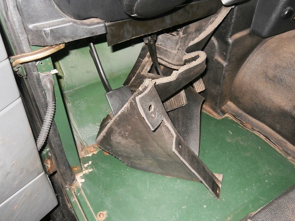
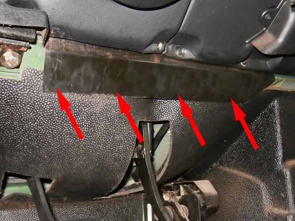
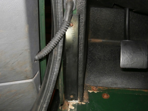
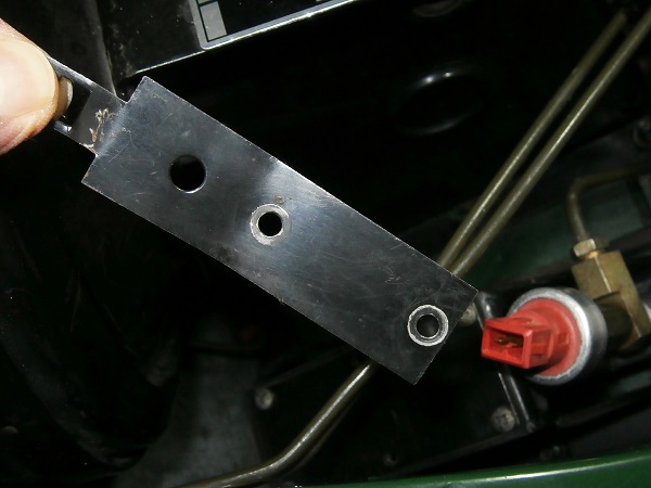
Pull the trim apart as far as it will go to access the clutch and brake pedals brackets fixing bolts. Pull by hand.
To facilitate the extraction of the trim and to have better access to the upper bolts, you can slightly deform the trim retaining plate (4th photo). Pull by hand.
Op 11
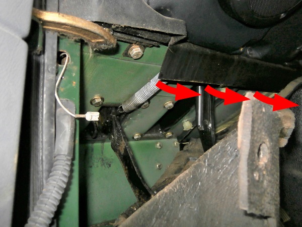
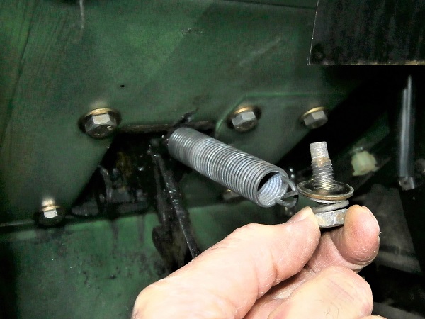
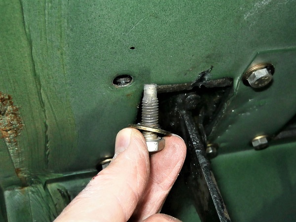
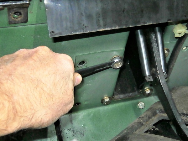
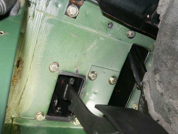
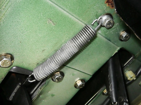
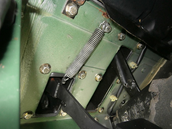
Unscrew the fixing bolt of the clutch pedal spring retaining bracket. Use the 13 mm spanner.
Unhook the spring from the pedal.
Retrieve the spring, the retaining bracket, the bolt and its 2 washers.
Op 12
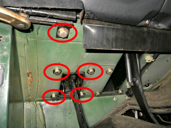
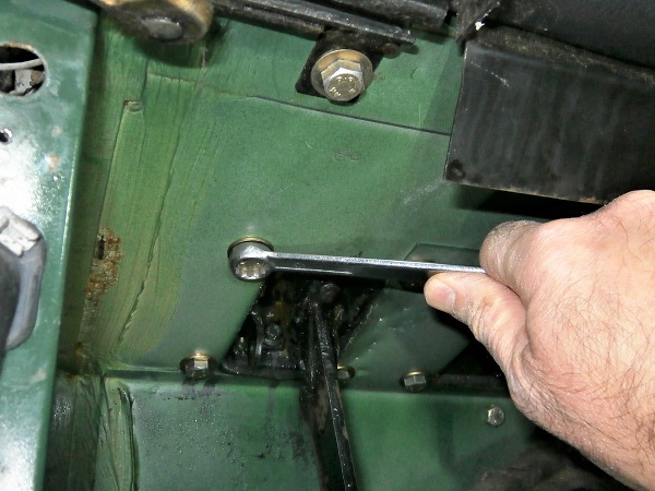
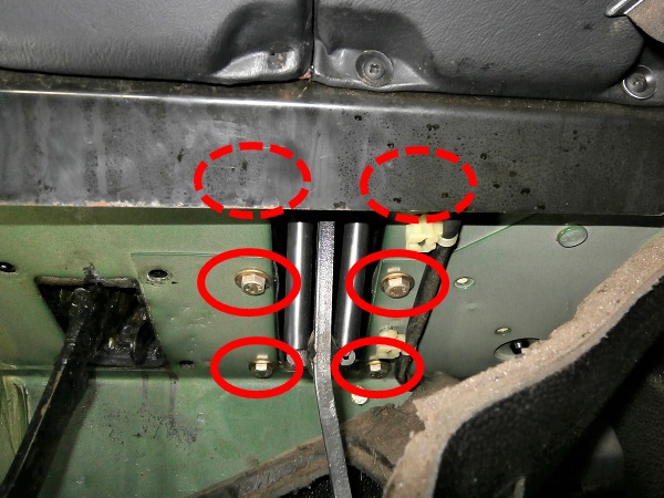
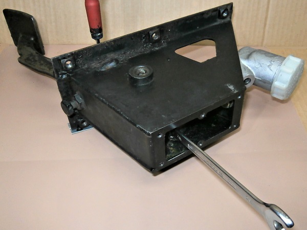
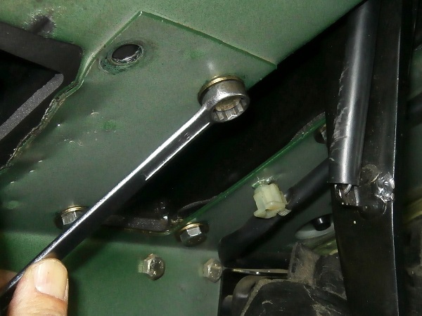
Unscrew the 5 other fixing bolts of the clutch pedal bracket. Use the 13 mm spanner.
Op 13
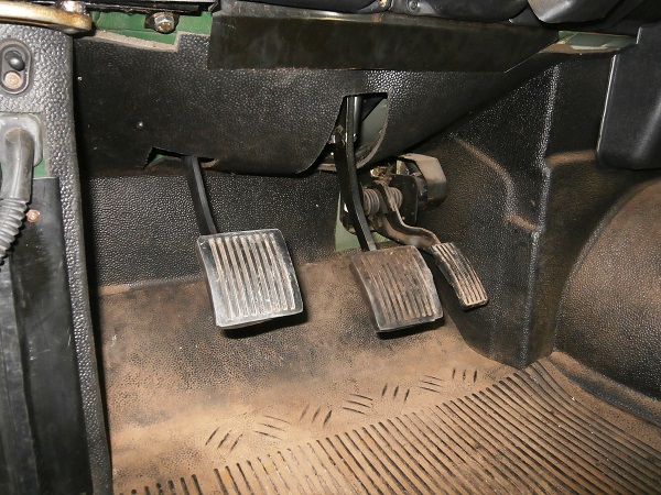
Unscrew the 6 fixing bolts of the brake pedal bracket. Use the 13 mm spanner.
Op 14
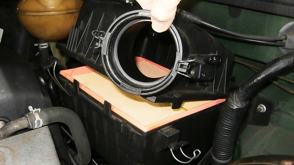
Remove the air duct (➔ see the tutorial ''Air filter change on Defender Td5'' Op 02 to 06).
We must remove the air duct. This will allow us to move the brake pedal bracket aside and thus free up enough space to be able to remove the clutch pedal bracket.
Op 15
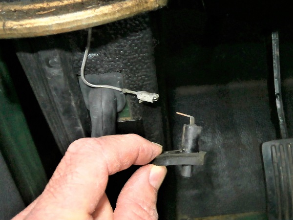
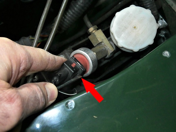
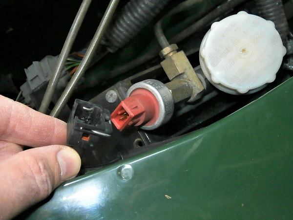
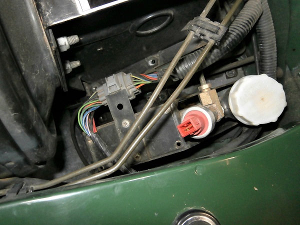
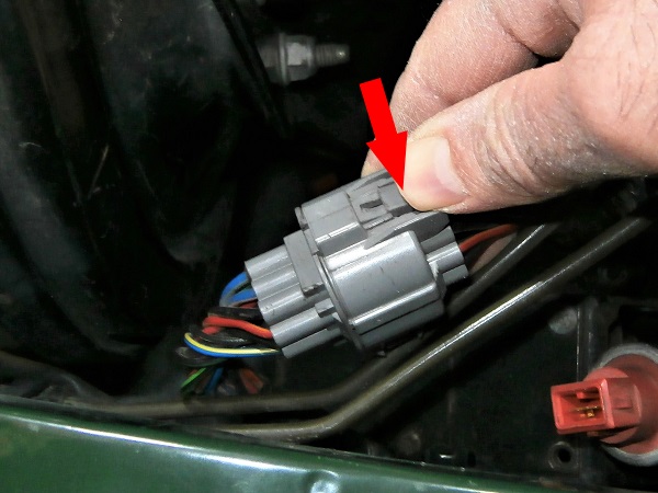
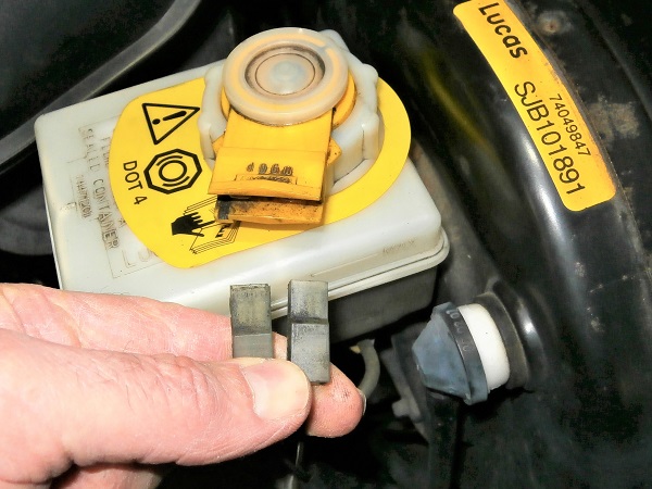
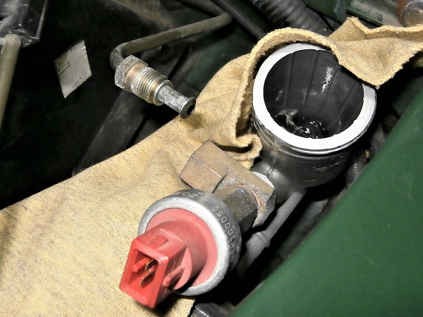
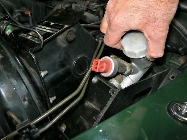
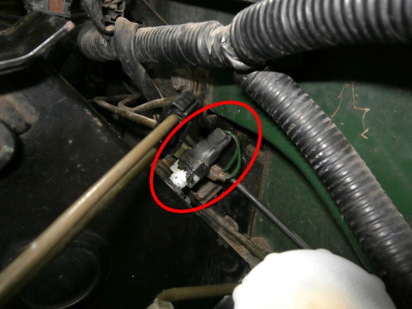
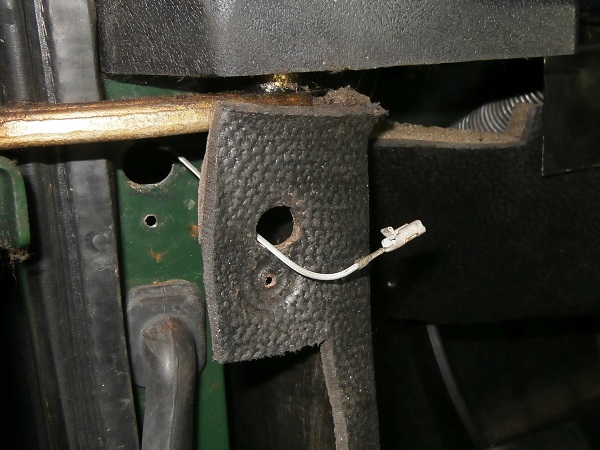
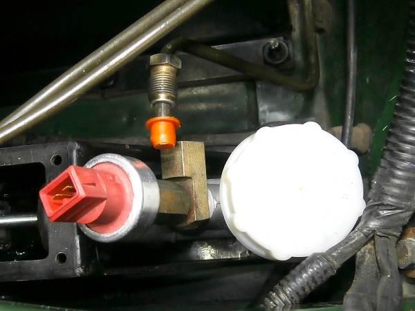
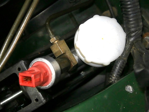
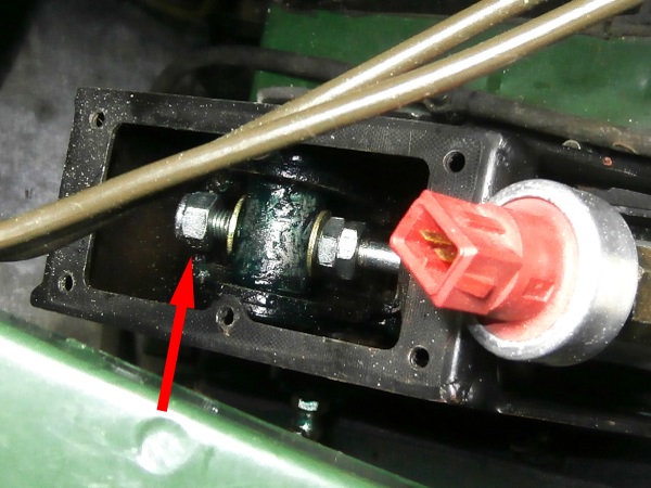
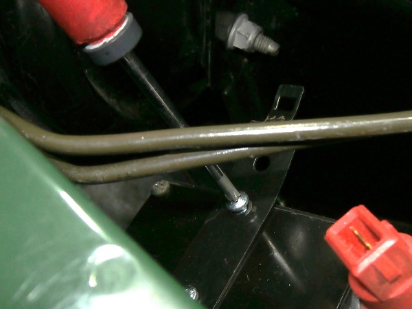
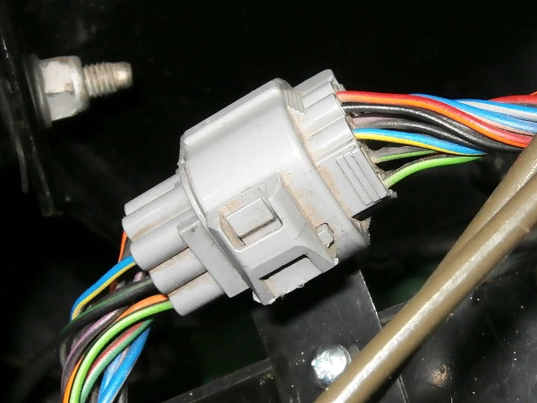
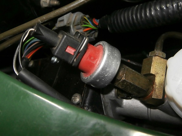
Disconnect the clutch master switch connector :
•
Press the metal locking clip with a small flathead screwdriver (2nd photo).
•
Pull on the connector by hand.
Op 16
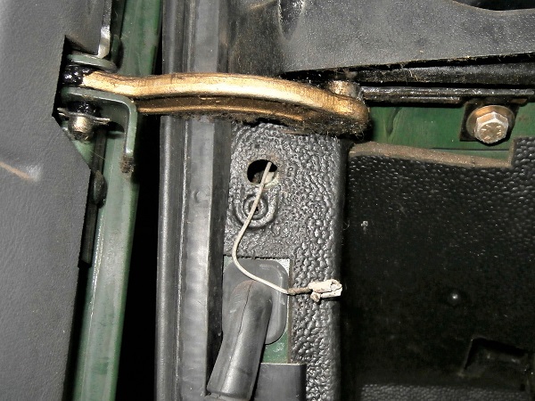
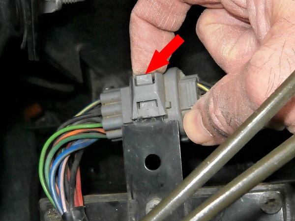
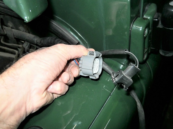
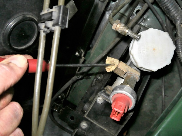
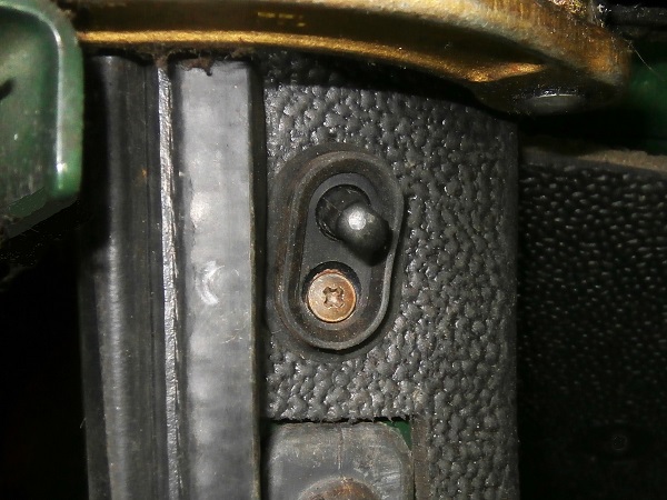
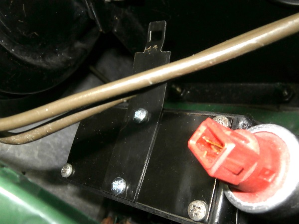
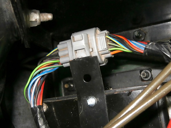
Unclip the connector located near the clutch pedal from its bracket :
•
Pull on the locking tab with your finger (2nd photo).
•
Pull on the connector by hand.
Op 17
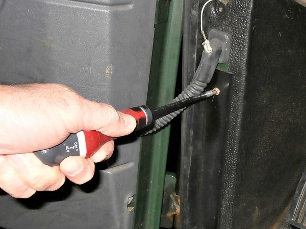
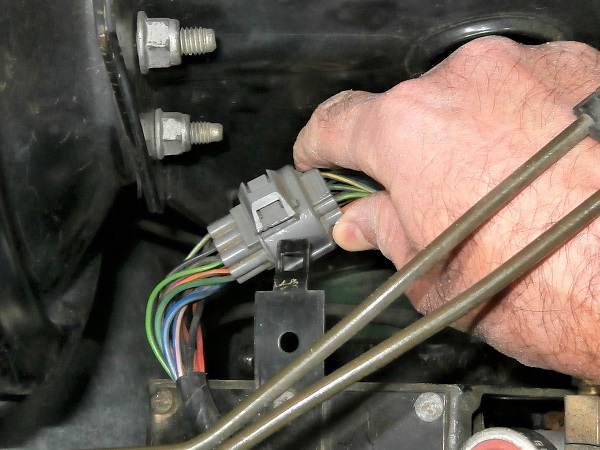
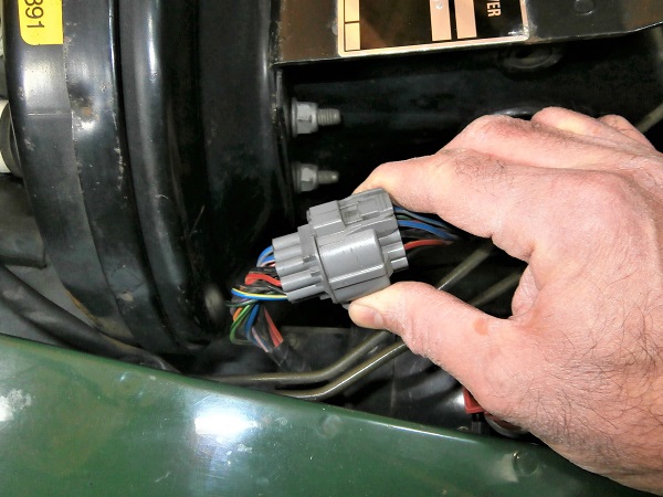
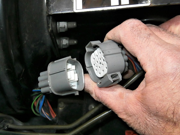
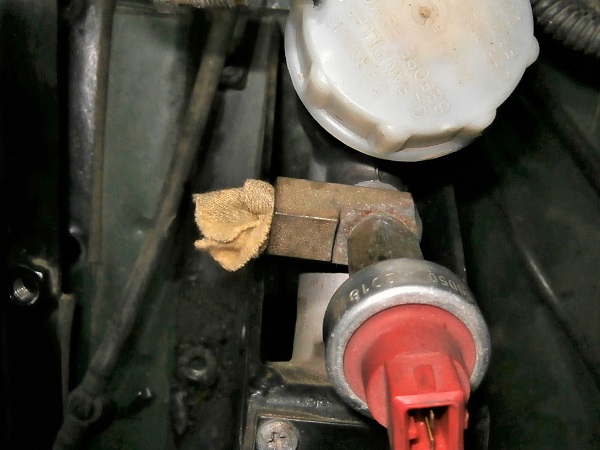
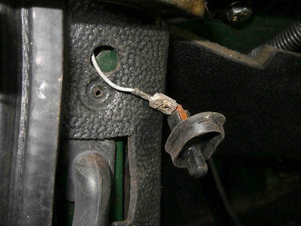
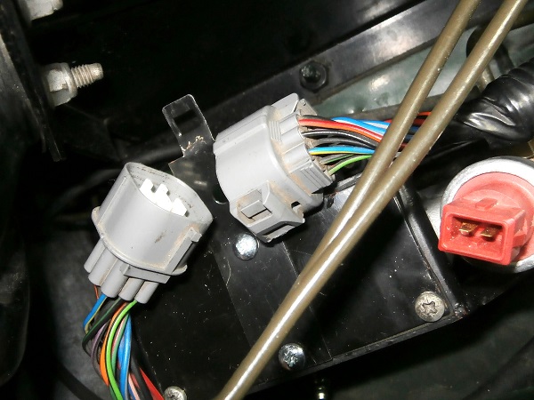
Disconnect the 2 connectors :
•
Press the locking tab with your finger (2nd photo).
•
Pull on the connectors by hand.
Op 18
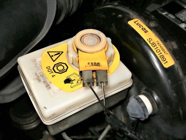
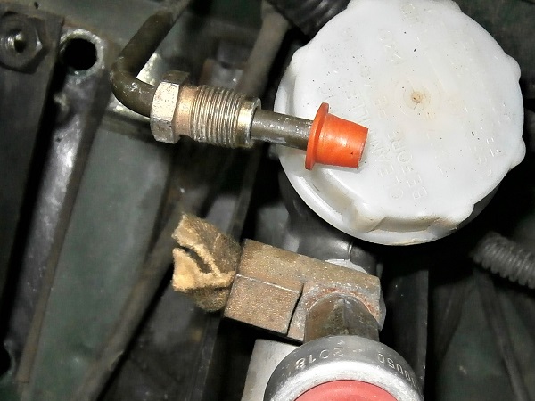
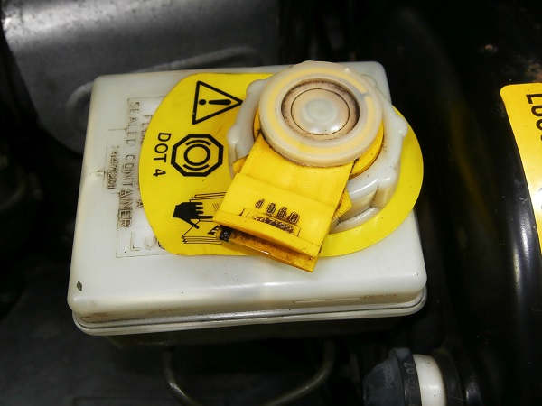
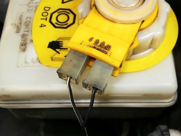
Disconnect the 2 connectors from the brake fluid level sensor. Pull by hand.
Op 19
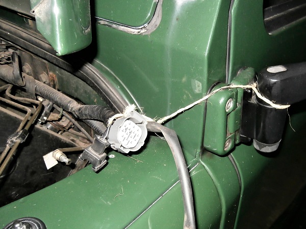
Move the electrical cables away from the working area. Secure them with a string.
Op 20
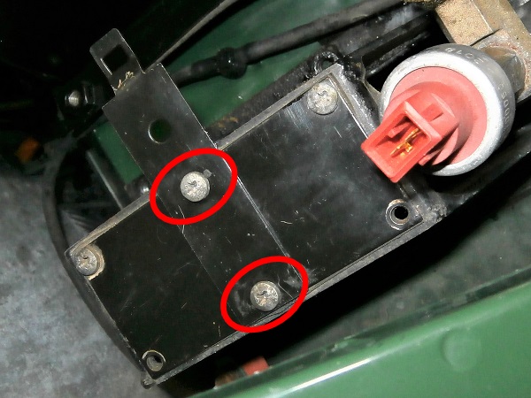
Unscrew the 2 fixing screws of the connector bracket. Use a Phillips screwdriver.
Remove the connector bracket. Lift by hand.
Op 21
Drain the clutch hydraulic system (➔ see the tutorial ''Clutch hydraulic system bleeding on Defender Td5'' Op 01 to 07).
Op 22
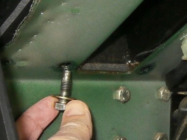
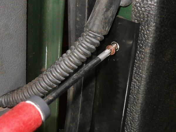
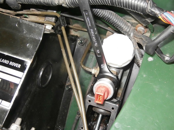
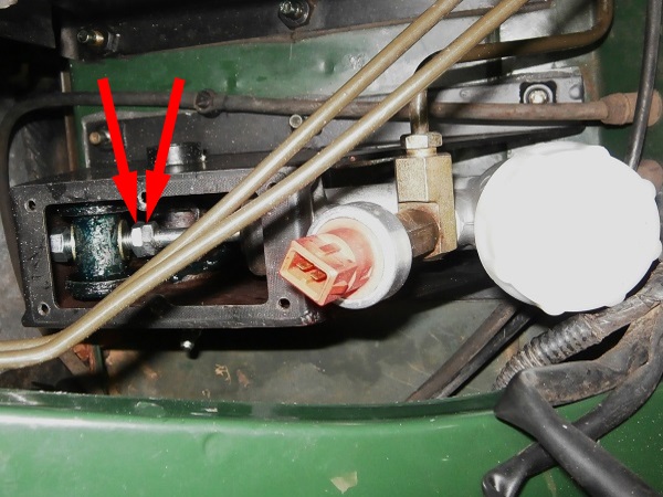
Unscrew the nut of the hydraulic pipe. Use the 13 mm spanner.
Beforehand, position a cloth to collect the drops of brake fluid.
Op 23
Plug the orifice of the master cylinder and the end of the hydraulic pipe. Use whatever you can find.
Op 24
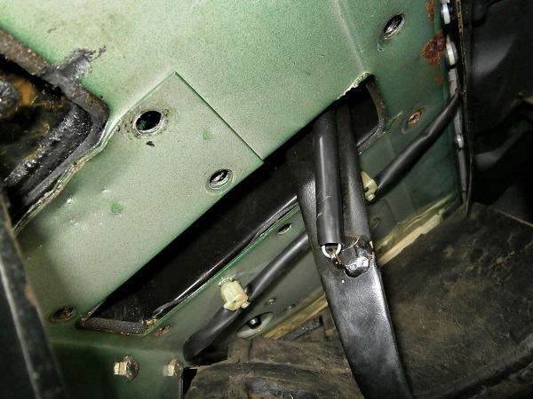
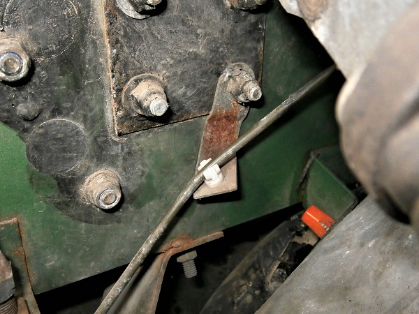
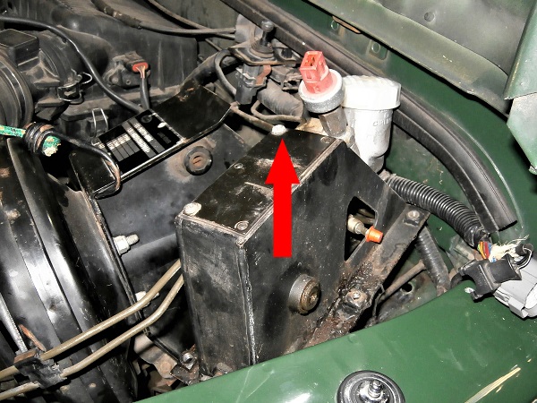
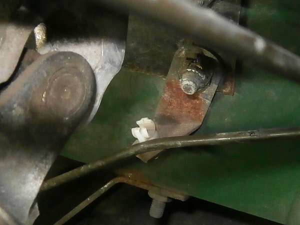
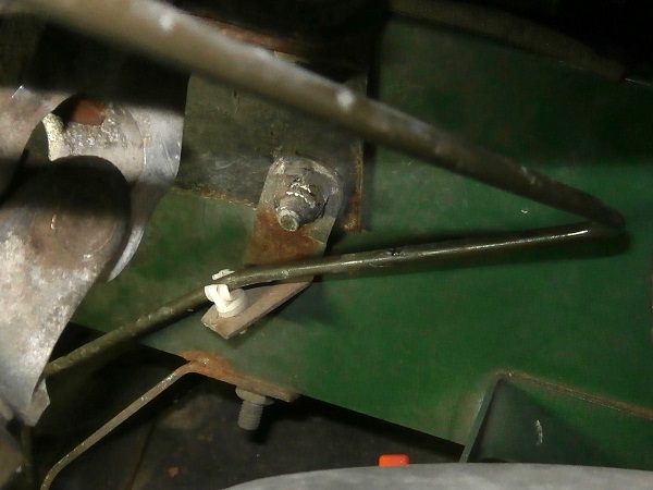
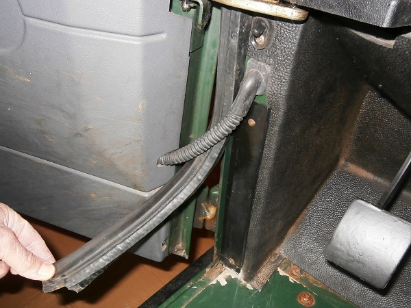
Unclip the front brake pipe (which goes down under the master cylinder) from its plastic clip. Pull by hand.
I'm not sure that this operation is essential but I preferred to give a little slack to avoid twisting this brake pipe when moving the brake pedal bracket.
Op 25
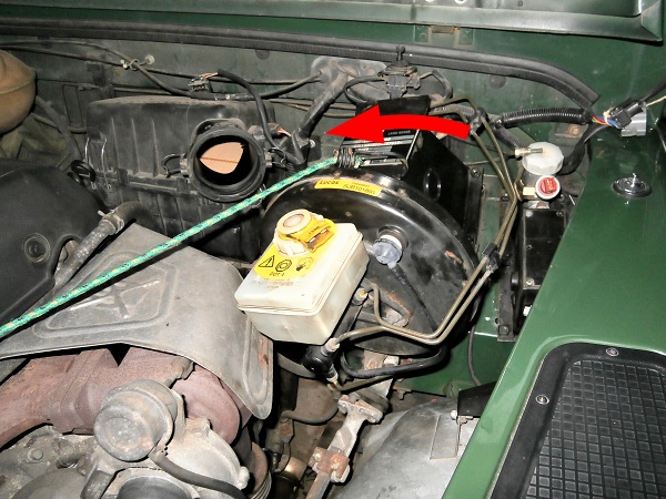
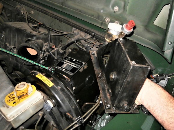
Move the brake pedal bracket towards the air filter to free up the working area above the clutch pedal.
Hold it in position with a rope.
Free up as much space as possible. You will see, every millimeter counts.
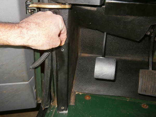
Op 26
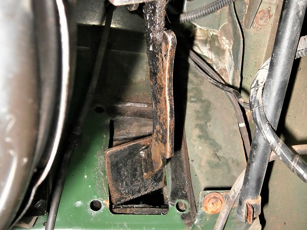
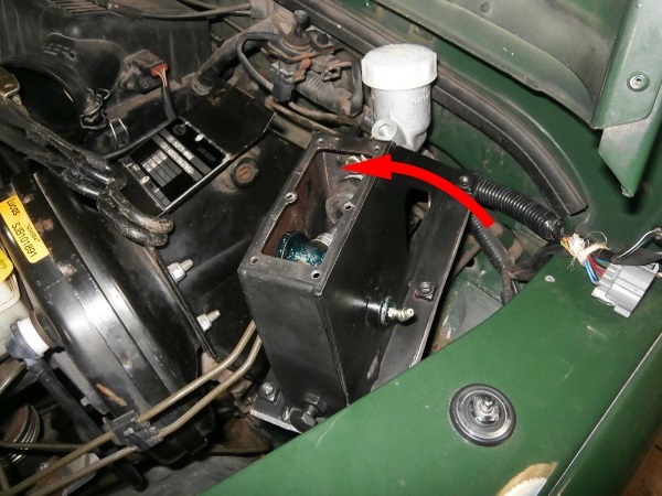
Lift the clutch pedal bracket and pass the pedal through the bulkhead. Lift by hand.
It is at this point that it gets complicated. The pedal is wider than the opening in the bulkhead.
You have to lift the clutch pedal bracket by pivoting it slightly counterclockwise and the pedal must pass. Unfortunately, this is easier said than done.
Op 27
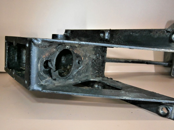
Finish removing the clutch pedal bracket. Lift by hand.
Slightly spread the brake pipes apart without deforming them to free the way.
Do not put the clutch pedal bracket on the front wing. It could scratch the paint.
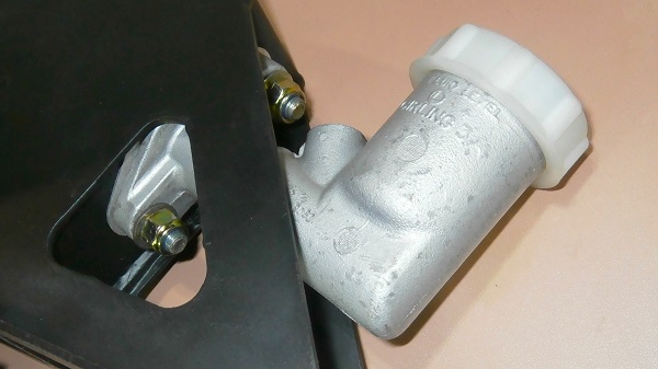
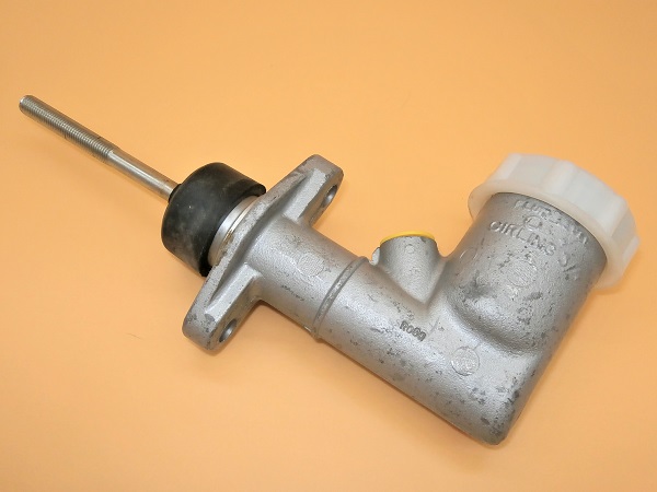
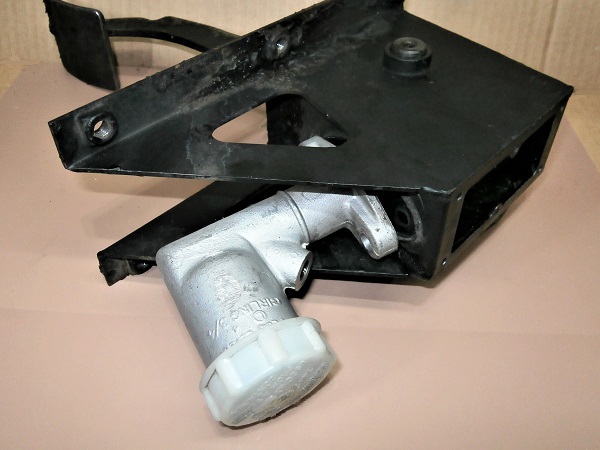
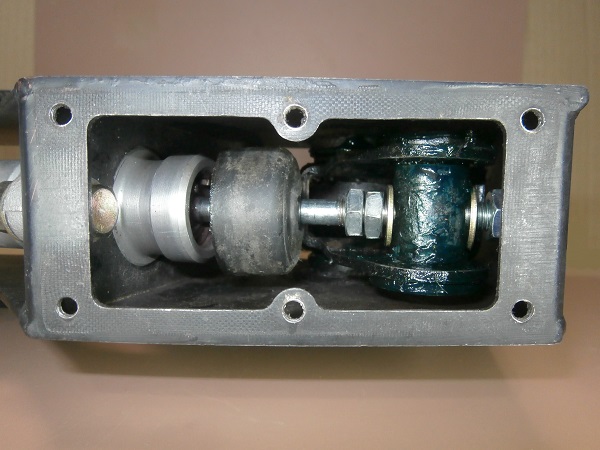
Remove the master cylinder from the pedal
Op 28
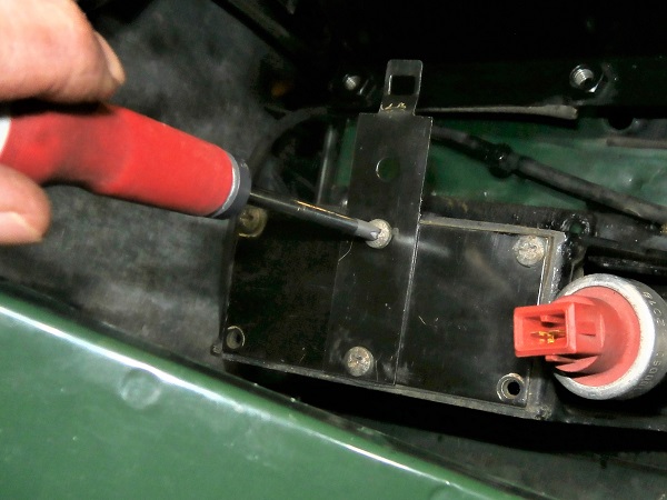
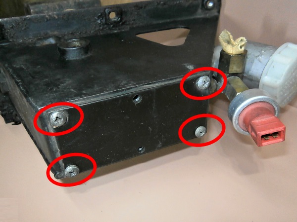
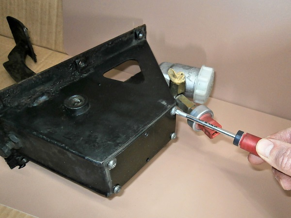
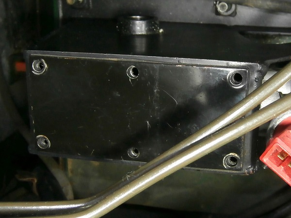
Unscrew the 4 fixing screws of the clutch pedal bracket cover. Use the Phillips screwdriver.
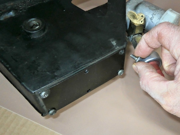
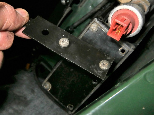
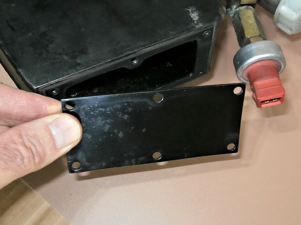
Op 29
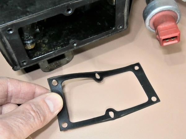
Remove the cover and its gasket.
Op 30
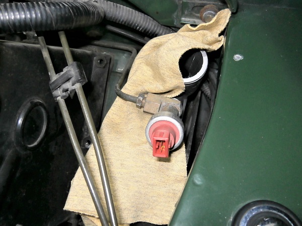
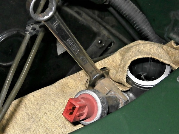
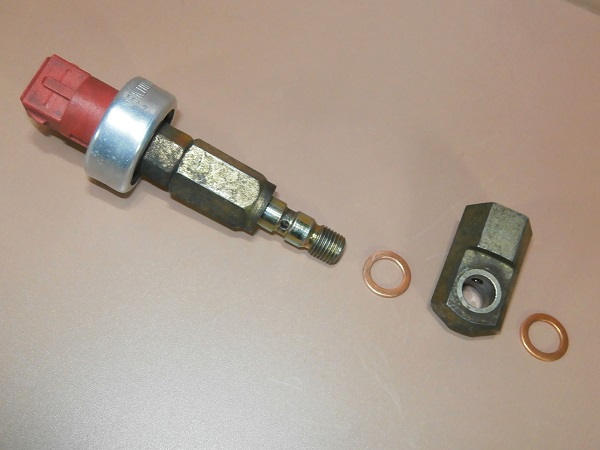
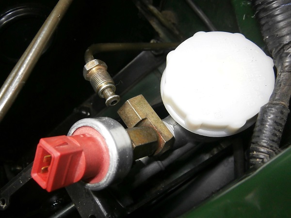
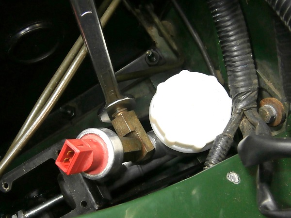
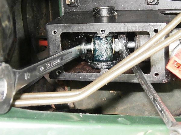
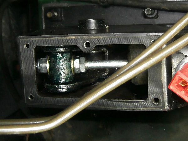
Unscrew the clutch master switch. Use a 5/8'' spanner.
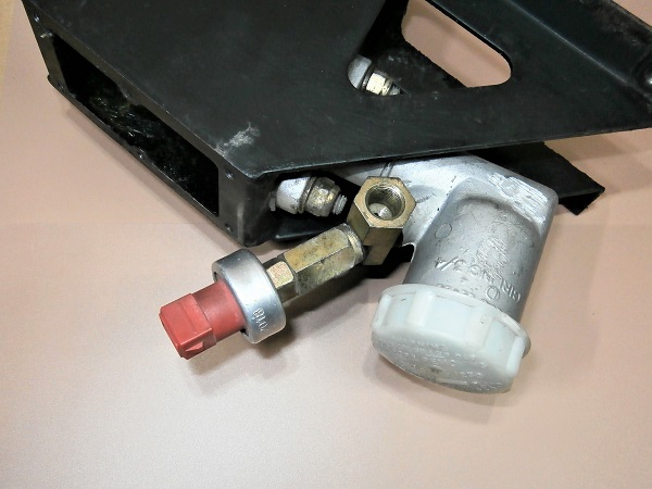
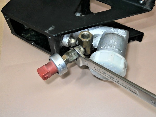
Op 31
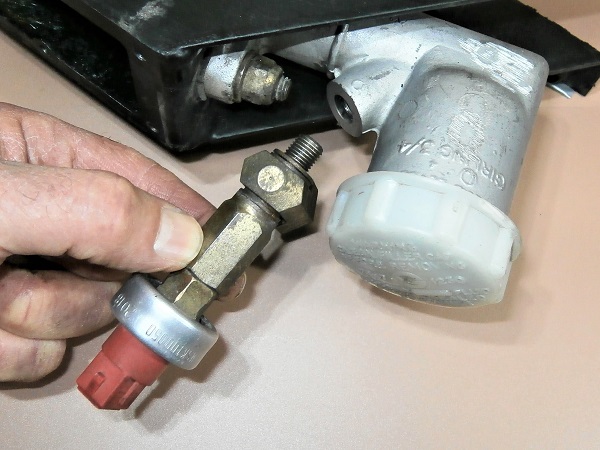
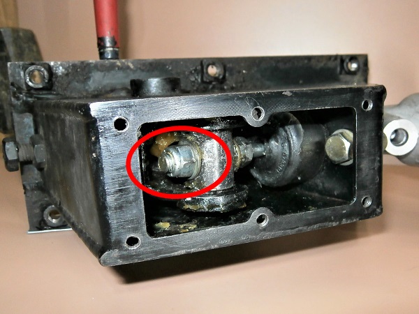
Depress the clutch pedal fully. Use a small screwdriver to lock it in position (1st photo).
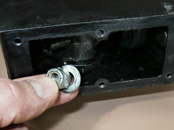
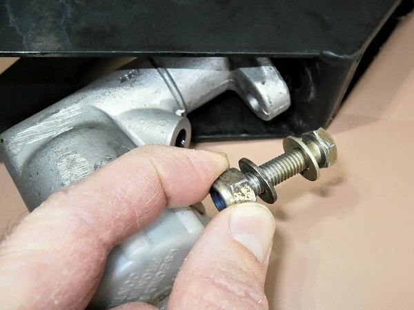
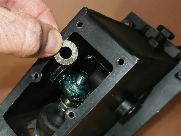
Unscrew the nut holding the master cylinder push rod to the pedal trunnion. Use a 1/2'' spanner.
Retrieve the nut and its washer.
If necessary, immobilize the master cylinder push rod in rotation with the multigrip pliers.
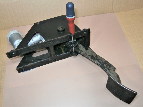
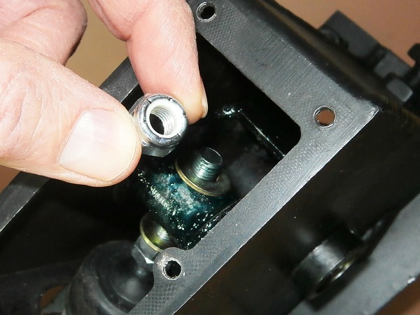
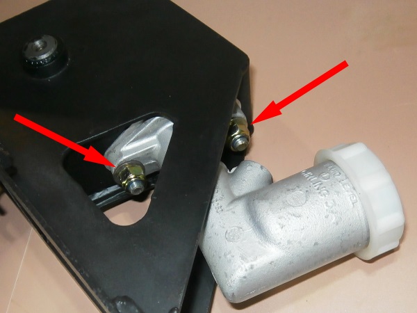
Op 32
Unscrew the 2 clutch master cylinder fixing nuts. Use a 13 mm spanner and socket.
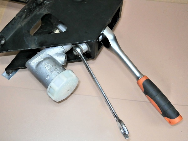
Op 33
Remove the clutch master cylinder from its bracket. Pull by hand.
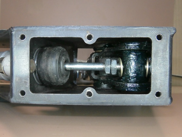
Fit the master cylinder on the pedal
Op 34
Remove the seal and thoroughly clean the master cylinder mounting surface. Use a cutter.
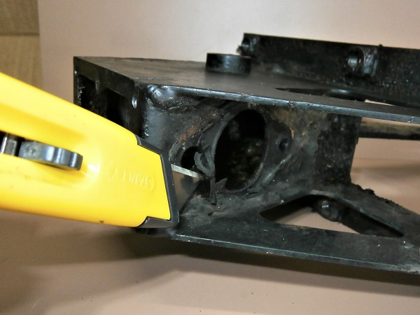
Op 35
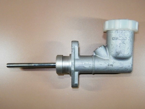
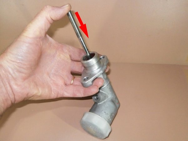
Remove the dust cover from the new clutch master cylinder (STC500100). Pull by hand.
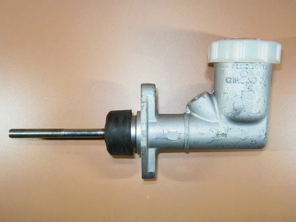
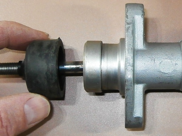
Op 36
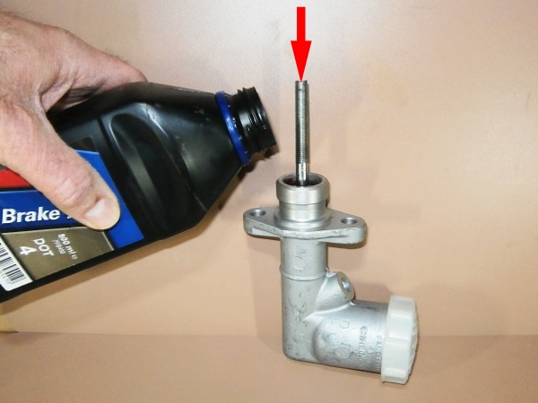
Lubricate the clutch master cylinder piston :
•
Push the push rod into the master cylinder. Press by hand.
•
Pour brake fluid into the bore.
•
Operate the push rod by hand several times.
Lubricating the piston is essential on a new clutch master cylinder. This prevents any initial sluggishness.
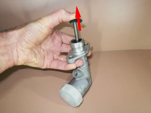
Op 37
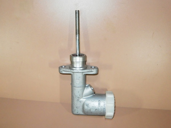
Fit the dust cover on the clutch master cylinder push rod.
Do not engage the dust cover on the body of the master cylinder. This will make it easier to mount the master cylinder on the clutch pedal bracket.
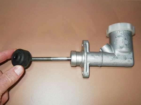
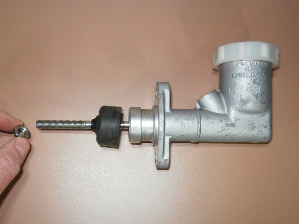
Op 38
Screw 2 nuts (NT605041L) onto the clutch master cylinder push rod.
Also fit a washer (WA108051L).
Fit the nuts and washer at the end of the thread. Do not tighten the nuts for now.
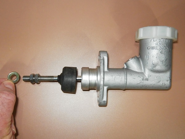
Op 39
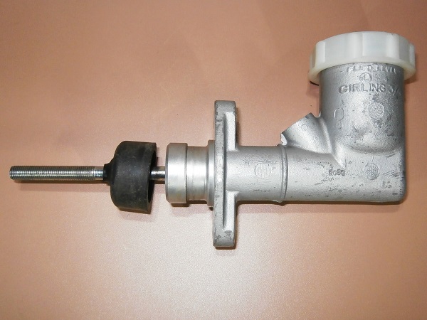
Fit the metal seal (592358) on the clutch master cylinder.
At this point, I should have mounted the ANR5308 seal. Unfortunately, I didn't have it in stock. So I mounted the metal seal 592358 which is normally dedicated to the Land Rover Series III.
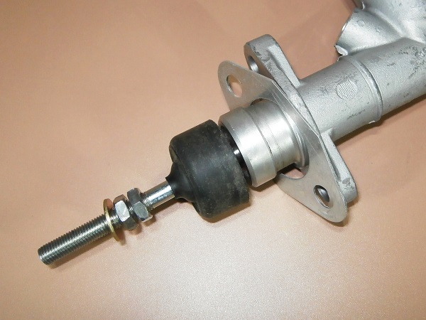
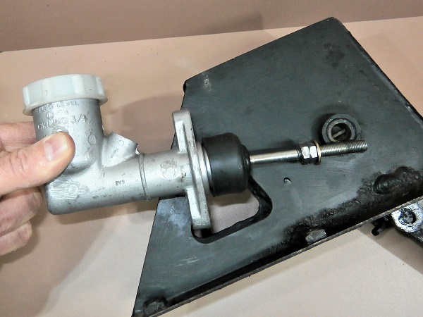
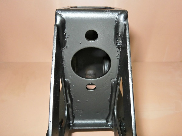
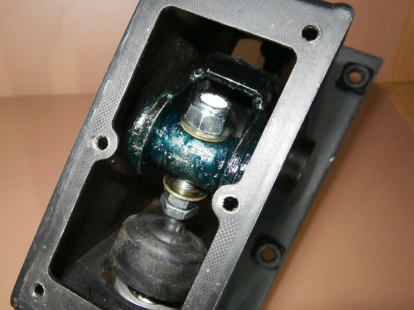
Op 40
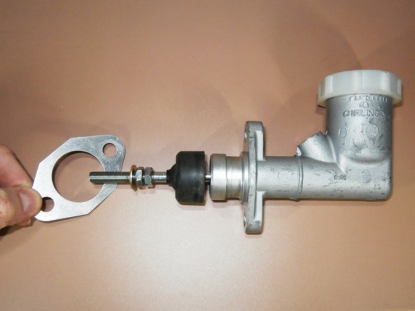
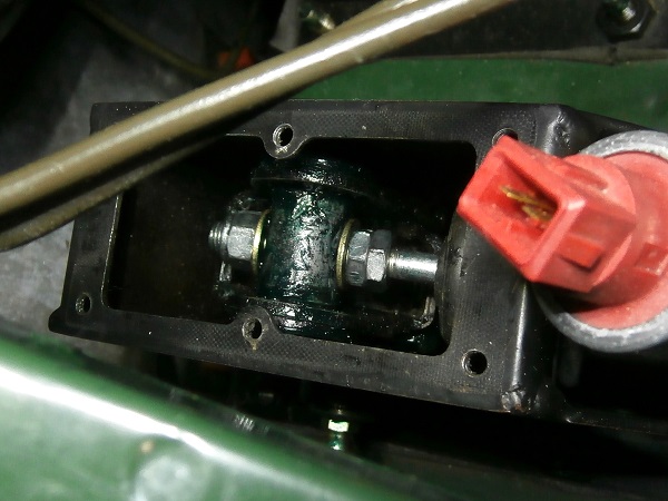
Fit the clutch master cylinder on its bracket.
Pass the master cylinder push rod through the pedal trunnion (3rd photo).
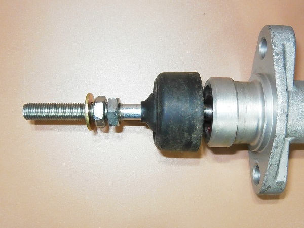
Op 41
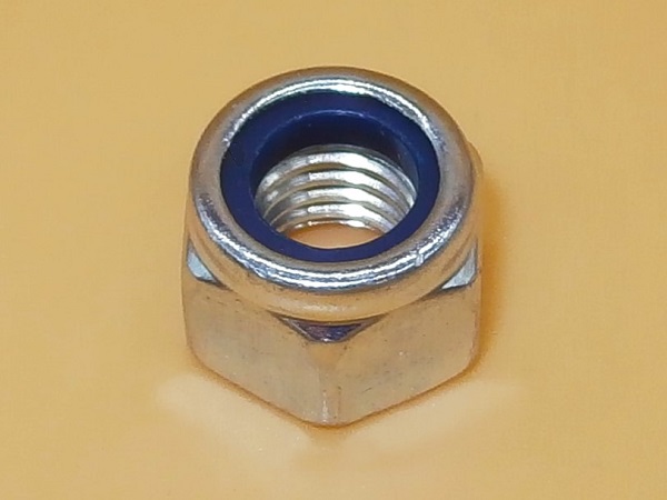
Fit a washer (WA108051L) and screw a new nut (NY605041L) onto the clutch master cylinder push rod.
As a safety measure, whenever a nyloc nut is removed, it is preferable to fit a new nut.
Screw the nut onto a few threads only. We will adjust the height of the clutch pedal later on the vehicle.
Op 42
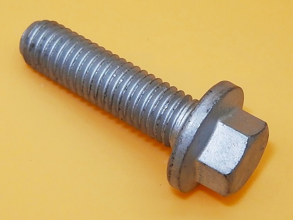
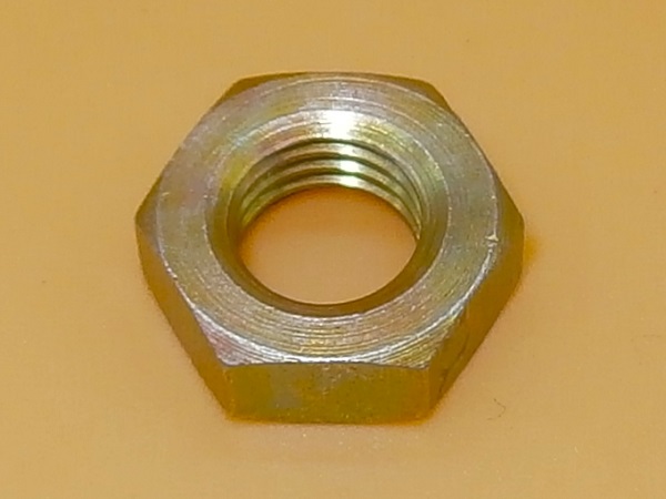
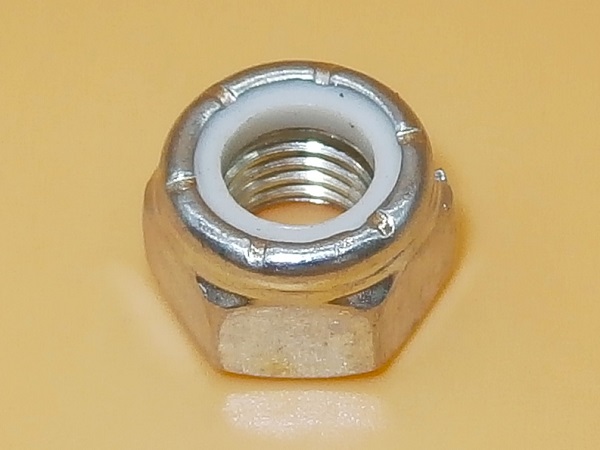
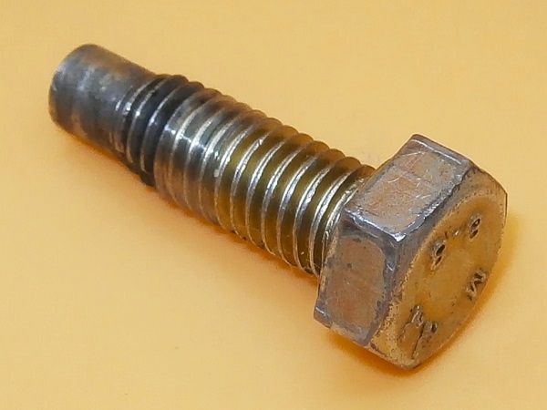
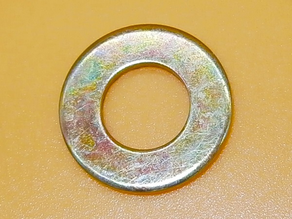
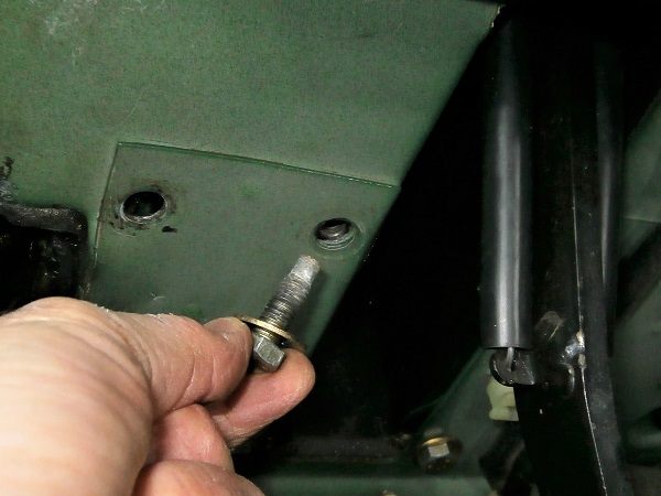
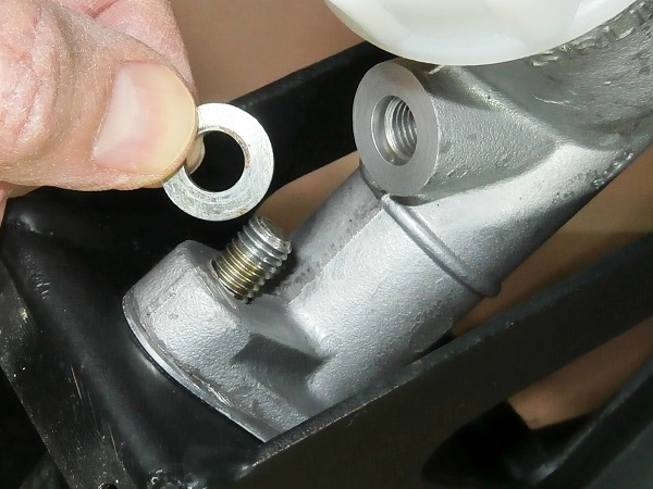
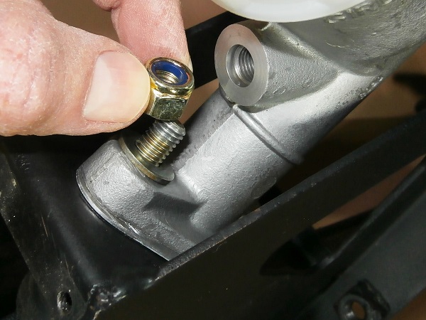
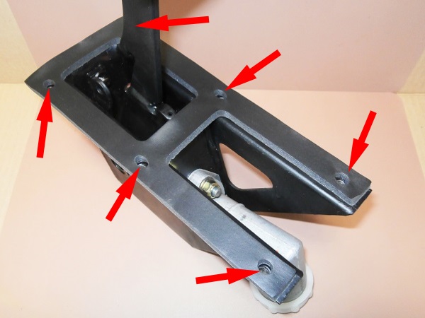
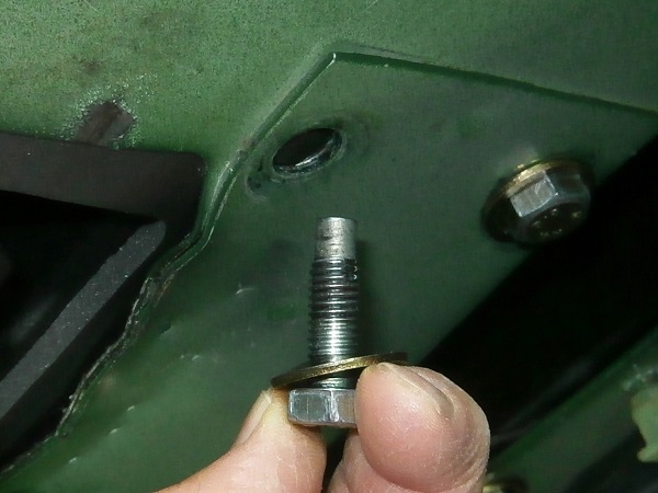
Fit the 2 master cylinder fixing bolts (FS108307L) with flat washers (WA108051L) and nuts (NY108041L).
Tighten the 2 nuts to 23 mN. Use the 13 mm socket and torque wrench.
Op 43
Fit the dust cover on the clutch master cylinder body. Push by hand.
Advertisement
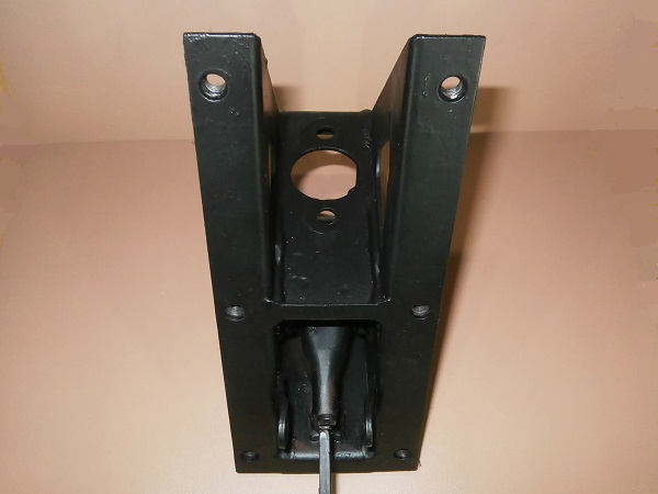
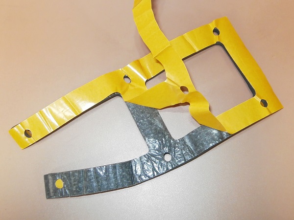
Fit the pedal + master cylinder assembly
Op 44
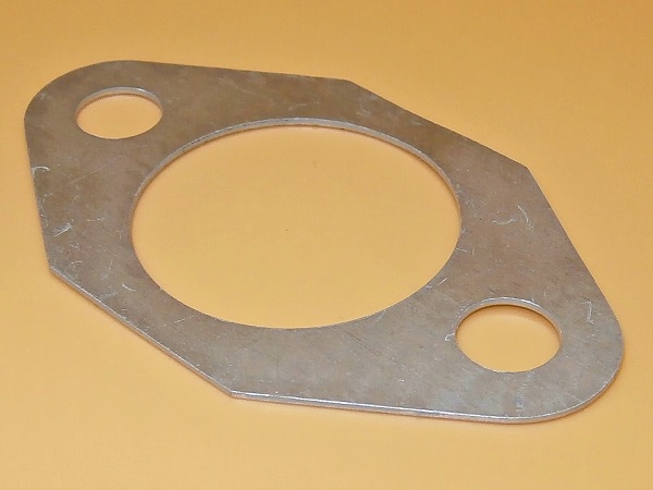
Remove the protective film from the new clutch pedal bracket gasket (ANR6332).
Stick the gasket to the bracket.
This gasket is adhesive. No need to provide glue to fix it on the bracket.
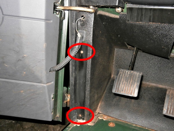
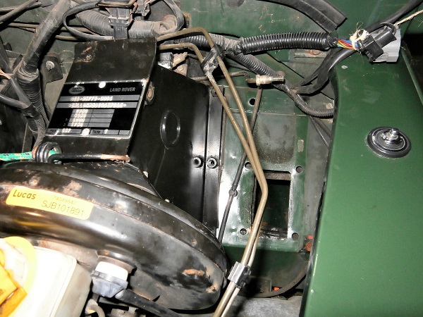
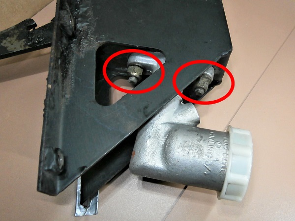
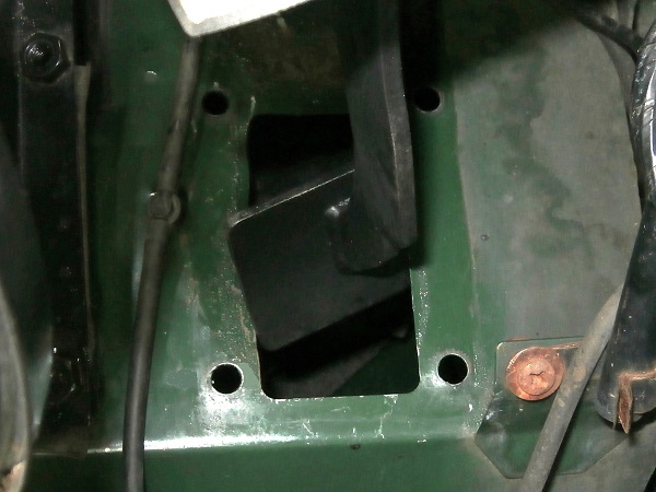
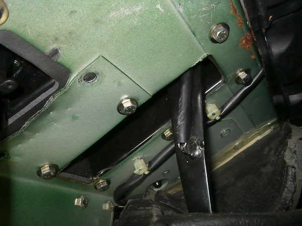
Align the 6 punch marks on the gasket with the 6 tapped holes for the pedal bracket fixing bolts on the bulkhead (3rd photo)
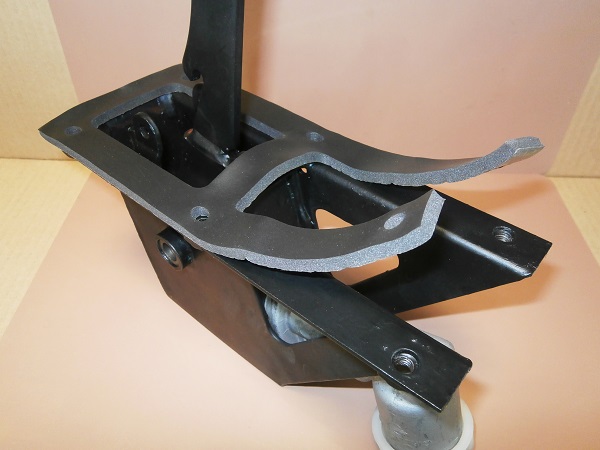
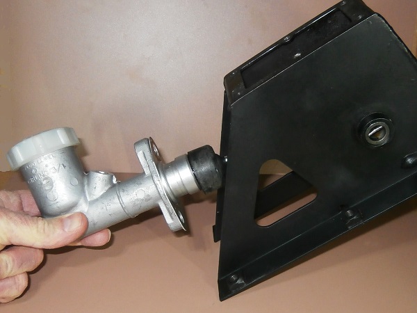
Op 45
Fit the clutch pedal bracket on the vehicle.
Proceed in the reverse way as when removing :
• Move the brake pedal bracket to free up space.
• Present the clutch pedal bracket slightly pivoted in a counterclockwise direction (2nd photo).
• Pass the clutch pedal through the bulkhead (3rd photo).
• Place the clutch pedal bracket in its final position.
• Move the brake pedal bracket to free up space.
• Present the clutch pedal bracket slightly pivoted in a counterclockwise direction (2nd photo).
• Pass the clutch pedal through the bulkhead (3rd photo).
• Place the clutch pedal bracket in its final position.
Check that no cable is trapped between the pedal bracket and the bulkhead.
Op 46
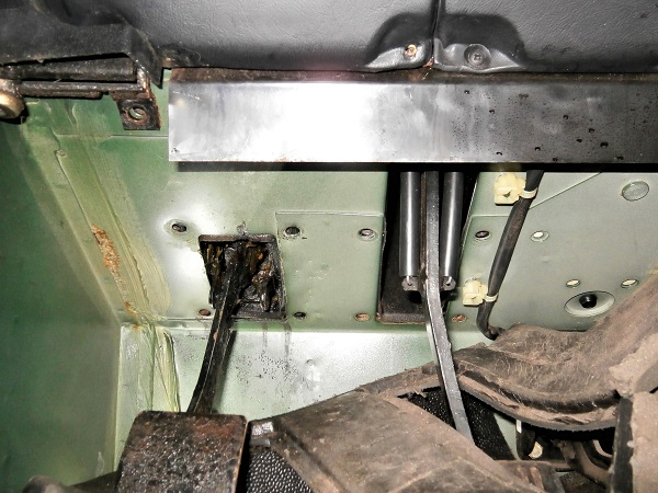
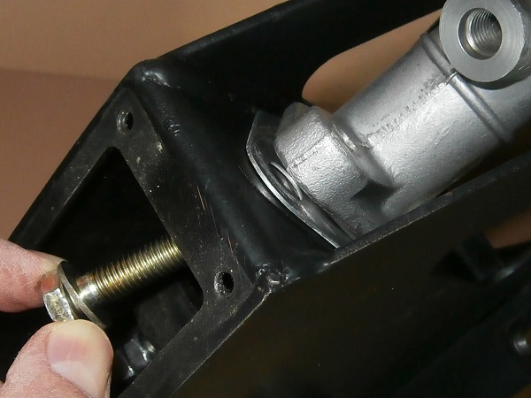
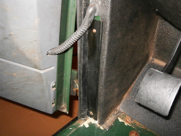
Fit the brake pedal bracket against the bulkhead.
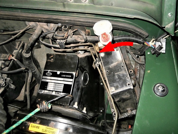
Do not damage the brake pedal switch which is located very close to the bulkhead (3rd photo).
Op 47
Clip the front brake pipe onto its plastic clip. Push by hand.
Take the opportunity to check that none of the brake pipes have been damaged when moving the brake pedal bracket.
Op 48
Screw in the 6 bolts (SYG500010) for fixing the brake pedal bracket with washers (WA108051L). Use the 13 mm spanner.
Op 49
Screw in 5 bolts (SYG500010) for fixing the clutch pedal bracket with washers (WA108051L). Use the 13 mm spanner.
Do not tighten these 5 bolts for now. Leave a little freedom to the clutch pedal bracket to be able to screw the 6th bolt (spring retaining bracket fixing) during the next operation.
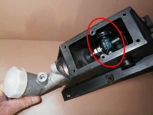
Op 50
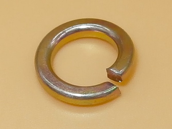
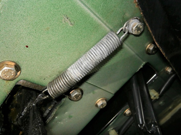
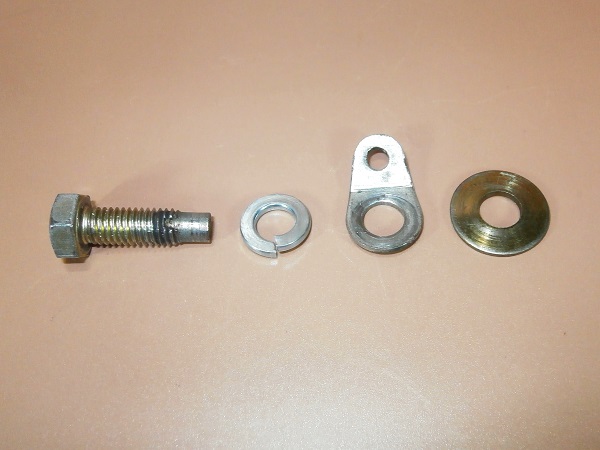
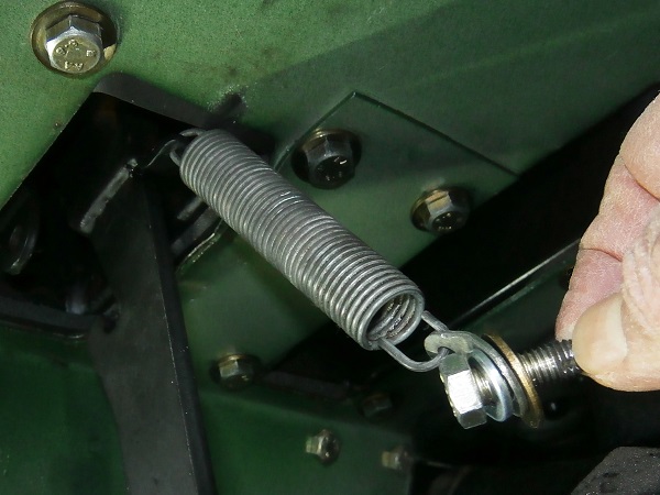
Prepare the bolt (SYG500010) for fixing the spring retaining bracket with 1 spring washer (WM600051L), the spring retaining bracket and 1 flat washer (WA108051L).
Fit the spring between the clutch pedal and its retaining bracket.
Screw in the bolt on the 6th fixing point of the clutch pedal bracket. Use the 13 mm spanner.
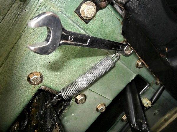
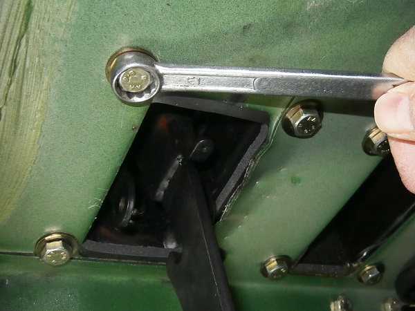
Op 51
Tighten the 12 fixing bolts (brake pedal bracket and clutch pedal bracket) to a torque of 23 mN. Use the 13 mm socket and torque wrench.
Op 52
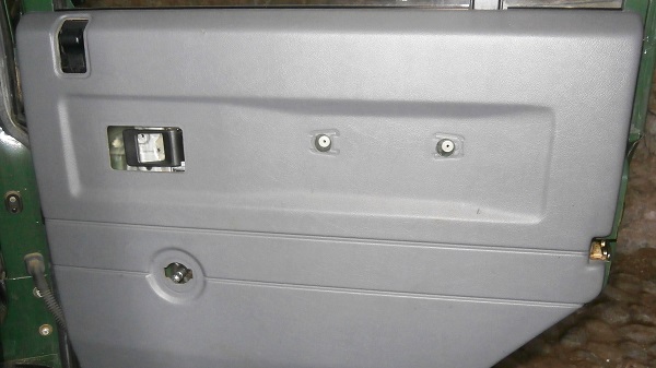
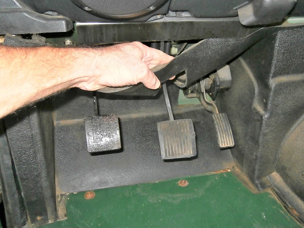
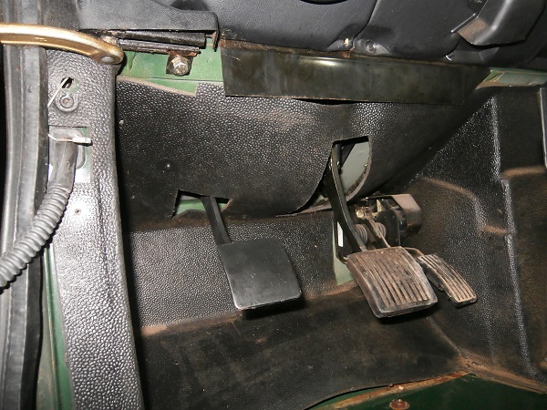
Fit the trim above the clutch and brake pedals.
Fit the trim retaining plate if you deformed it during disassembly (3rd photo). Push by hand.
Op 53
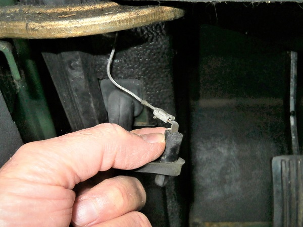
Pass the courtesy light switch cable through the trim and connect the switch.
Op 54
Fit the courtesy light switch and screw in its fixing screw. Use the Phillips screwdriver.
Op 55
Fit the trim retainer and screw in its 2 fixing screws. Use the Phillips screwdriver.
Op 56
Fit the door seal. Push by hand.
Op 57
Fit the clutch pedal rubber. Push by hand.
Fit the driver's side rubber floor mat.
Op 58
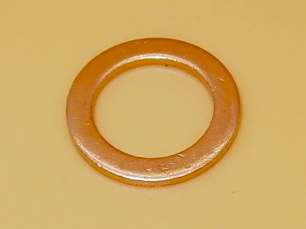
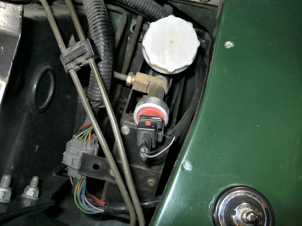
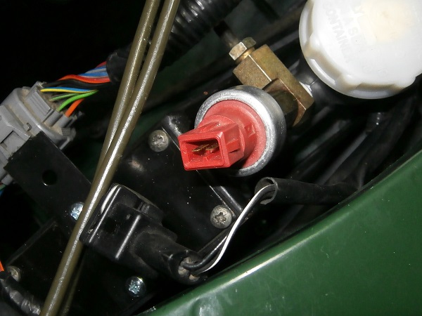
Prepare the clutch master switch with the banjo fitting and 2 new sealing washers (233220).
Screw the switch onto the clutch master cylinder.
Don't skimp on the sealing washers. Always install new ones.
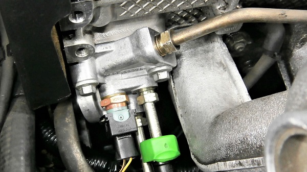
Screw in the switch without tightening it for now. We will tighten it when the banjo fitting is aligned with the hydraulic pipe.
Op 59
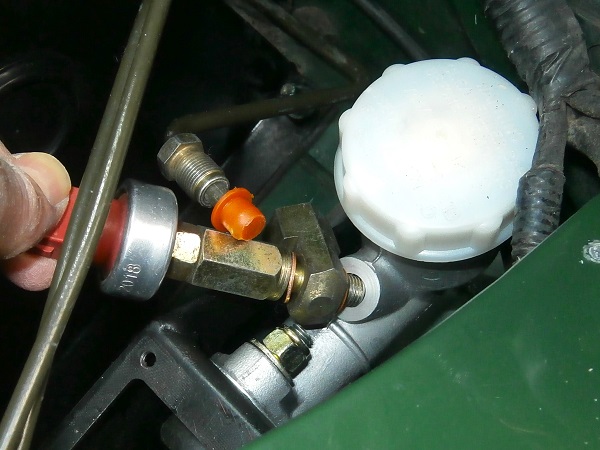
Align the banjo fitting with the hydraulic pipe.
Engage the hydraulic pipe in the banjo fitting and tighten the nut. Use the 13 mm spanner.
The hydraulic pipe nut must be tightened to 15 mN. This operation requires a specific torque wrench with a flat spanner. If you don't have this type of wrench like me, tighten moderately.
Op 60
Tighten the switch onto the clutch master cylinder. Use the 5/8'' spanner.
The switch must be tightened to 15 mN.
Adjust the clutch pedal travel
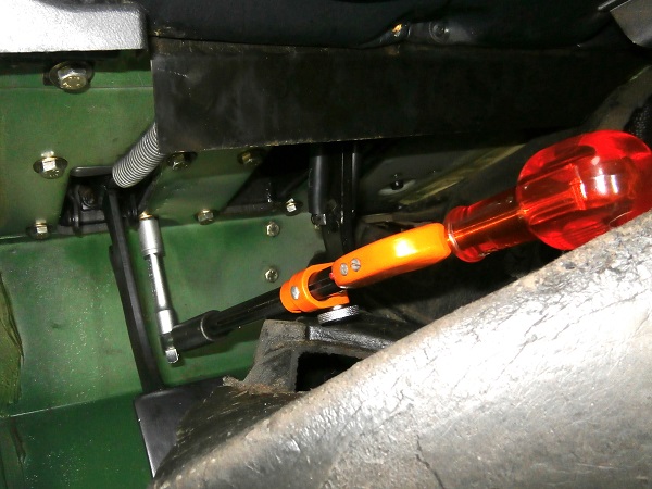
Op 61
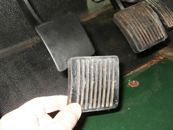
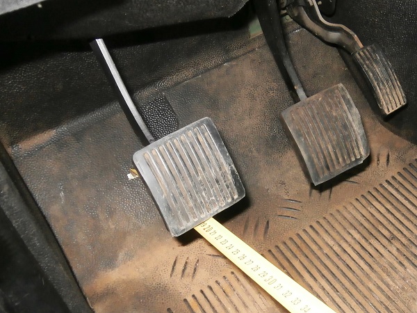
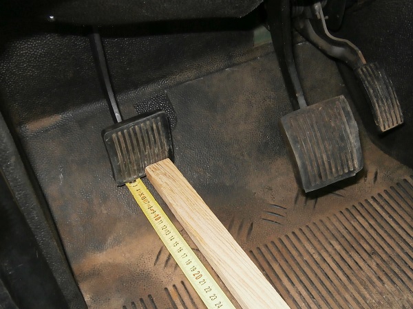
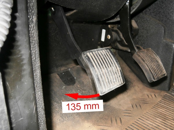
Actuate the clutch pedal from the rest position (1st photo) to the fully depressed position (2nd photo).
Measure the pedal travel between these 2 positions.
Once the clutch pedal is adjusted, the travel should be 135 mm.
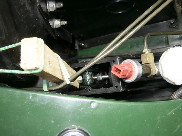
Op 62
Move the 2 adjusting nuts on the clutch master cylinder push rod to adjust the pedal travel to 135 mm.
Op 63
Tighten the 2 adjusting nuts against each other. Use two 1/2'' spanners (a 13 mm spanner will also do the trick).
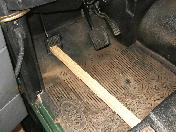
For this operation, the nuts are easier to access when the clutch master cylinder push rod is pushed in and the pedal is free. Wedge the rod with whatever you can find (1st photo).
The 2 adjusting nuts must be tightened to 23 mN. Unfortunately, it is impossible to access them with a torque wrench.
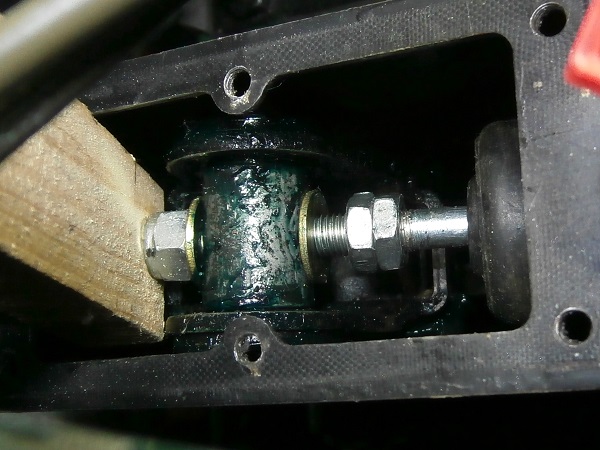
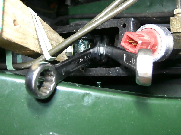
Op 64
Tighten the locking nut on the clutch master cylinder push rod. Use two 1/2'' spanners.
For this operation, the locking nut is easier to access when the clutch pedal is fully depressed. Wedge the pedal with whatever you can find (1st photo).
To immobilize the master cylinder push rod in rotation, block one of the adjusting nuts.
The locking nut must be tightened to 23 mN.
Op 65
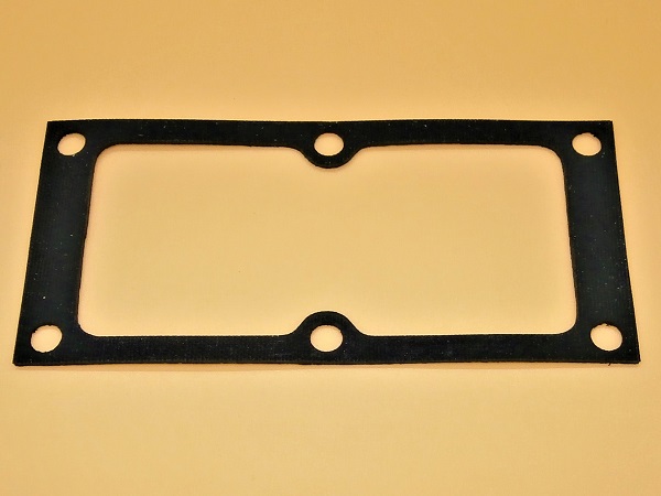
Fit the gasket (272819) and the cover on the clutch pedal bracket.
Screw in 4 of the 6 screws (SL510031) for fixing the cover. Use a Phillips screwdriver.
The other 2 screws will be installed when the connector bracket is put in place.
The screws must be tightened to 3 mN.
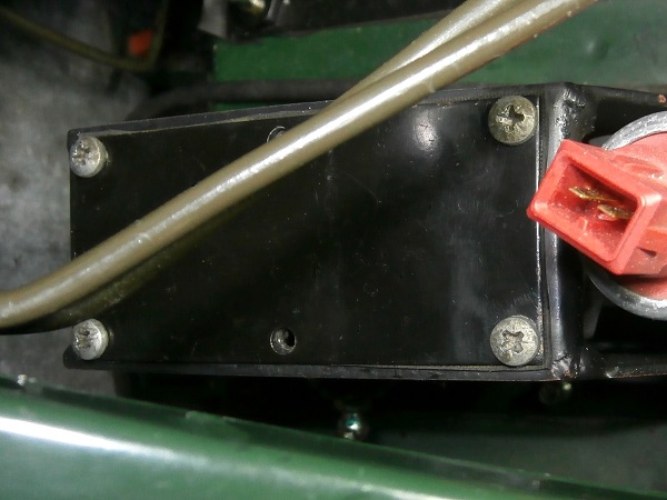
Op 66
Fit the connector bracket on the clutch pedal bracket.
Screw in the 2 fixing screws (SL510031). Use a Phillips screwdriver.
Op 67
Put the electrical cables back in place around the clutch pedal bracket.
Connect the 2 connectors to the brake fluid level sensor. Push by hand.
The 2 connectors do not have a specific position. It doesn't matter which order you connect them to the brake fluid level sensor.
Op 68
Connect the 2 connectors of the wiring harness. Push by hand.
Clip the connectors onto the bracket. Push by hand.
Op 69
Connect the clutch master switch connector. Push by hand.
Advertisement
Bleed the clutch hydraulic system
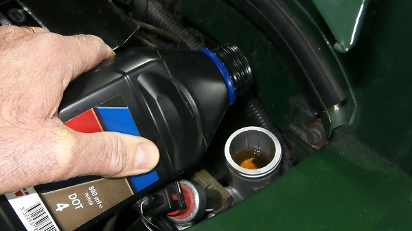
Op 70
Fill and bleed the clutch hydraulic system (➔ see the tutorial ''Clutch hydraulic system bleeding on Defender Td5'' Op 14 to 21).
Op 71
Fit the air duct (➔ see the tutorial ''Air filter change on Defender Td5'' Op 22 to 26).
Op 72
Take a road test to check that the clutch is working perfectly.
Upon return, check that there are no brake fluid leaks at the banjo fitting at the clutch master cylinder outlet.
The End