
This tutorial is also available in French
➔

In-tank fuel pump change on Defender 110 Td5
Vehicle ➔ Defender 110 Td5 2002
Difficulty ➔ Medium

Time ➔ 4 hours
Summary
Advertisement
Advertisement

Recommendations

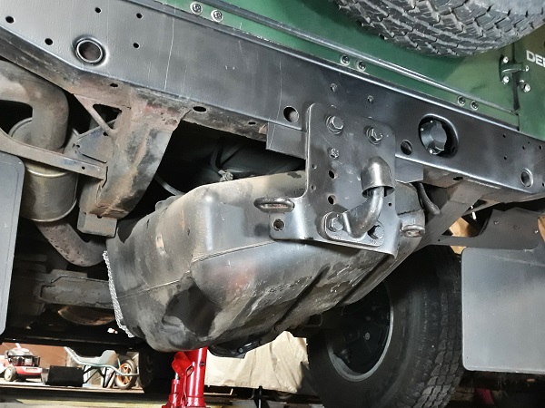
The in-tank fuel pump is located under the rear floor above the fuel tank.

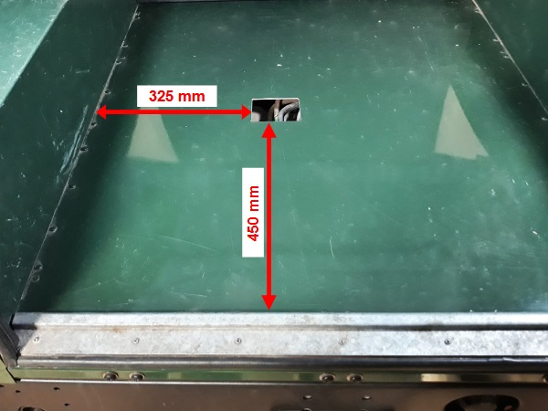
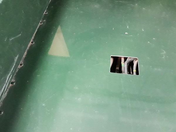
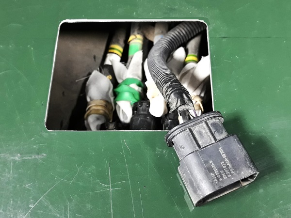
To make our task easier, we have cut a small opening in the boot floor of the Defender 110. This opening gives us direct access to the 4 hoses and the electrical cable that are connected to the in-tank fuel pump. This trick will make it easier for us to disconnect the hoses and the connector.

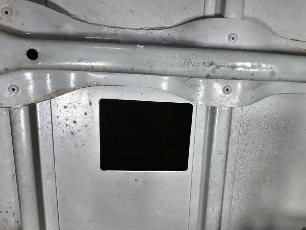
We could have cut a larger opening in the floor. This would have allowed us to change the in-tank pump without having to remove the tank. Unfortunately, this would also have forced us to cut two of the floor crossmembers (see the underfloor crossmembers in the photo). We did not choose this option because we prefer not to weaken the body structure.
The dimensions of the opening in the floor above are suitable for the Defender 110 SW. If you have a Defender 90, you will find the dimensions on the
Land Mag website (➔ see the tutorial).
The fuel tank capacity of the Defender 110 Td5 is 70 litres. Empty the tank before removing it. It will be much easier.
The fuel tank is a very bulky part. Removing it is not easy. Get help from a friend, it will be much easier.
On our Defenders that are starting to accumulate years, the tank is often polluted by sludge and algae. Take advantage of removing the tank to drain and clean it. Once the fuel pump is removed, you can reach inside the tank for optimal cleaning.
There are 2 in-tank fuel pumps for Defender Td5 :
• WFX000250: fitted on Defender Td5 90.
• WFX000260: fitted on Defender Td5 110 and 130.
• WFX000250: fitted on Defender Td5 90.
• WFX000260: fitted on Defender Td5 110 and 130.
This time, we invested in a genuine Continental VDO fuel pump. It's relatively expensive, but it's good quality. Previously, we had fitted an aftermarket Hitachi pump. That pump was three times cheaper, but it was very noisy and unfortunately failed after a year.
Changing the fuel pump generates an air inlet in the fuel system. It will therefore be imperative to bleed the fuel system before restarting the engine. This operation is very simple (see Op 55).
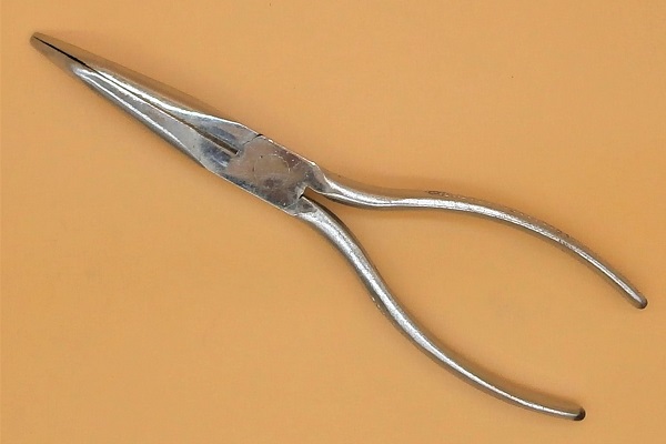
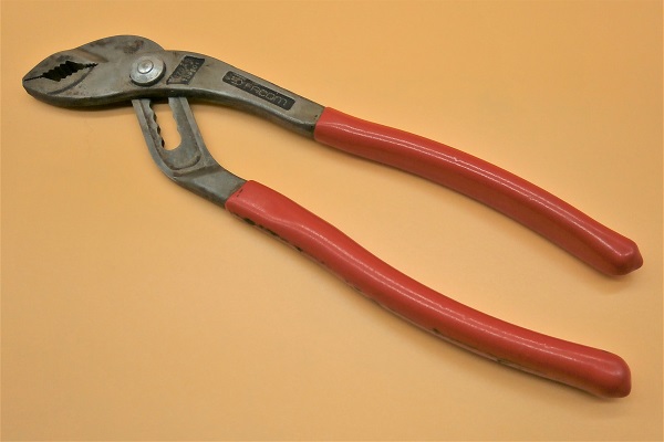
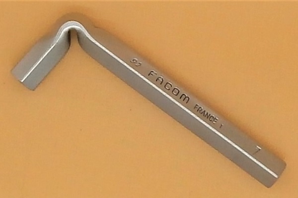
Required Tools
Sponsored links by

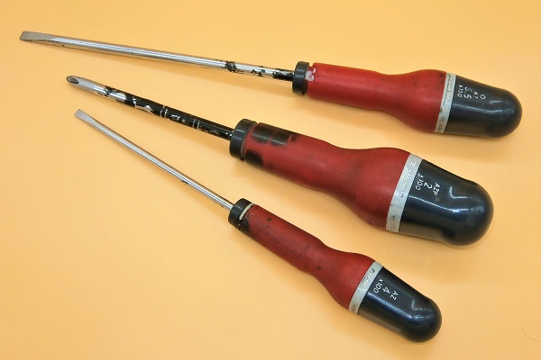
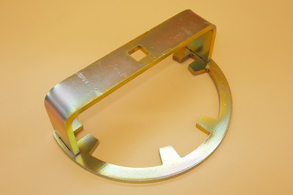
When writing this tutorial, we used tool reference PM353 to unscrew the locking ring of the fuel pump, but you can also use tool reference DA1209.
If you don't have any of these tools, you can use a hammer and punch. Simply strike the lugs on the ring to unscrew it.
If you don't have any of these tools, you can use a hammer and punch. Simply strike the lugs on the ring to unscrew it.
Spare Parts
Sponsored links by


Packaging :
•
WFX000260 : The in-tank fuel pump is sometimes supplied with its seal (WGQ500020). Check before ordering.
• All the above parts are sold individually.
• All the above parts are sold individually.
Advertisement
Remove the fuel tank
Op 01
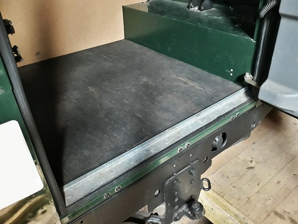
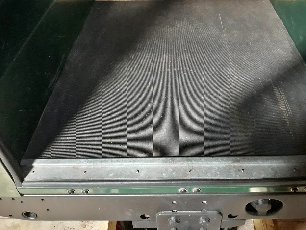
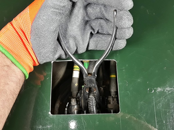
Move the rear floor rubber mat aside and clear the access opening to the in-tank fuel pump.
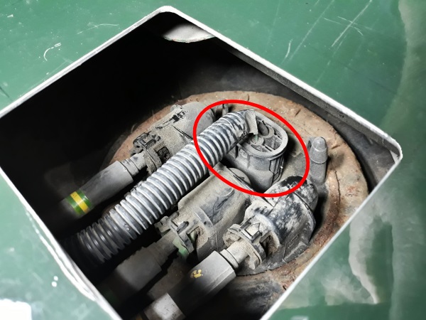
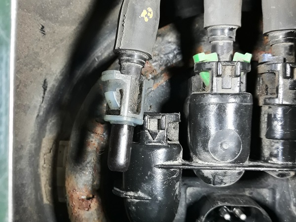
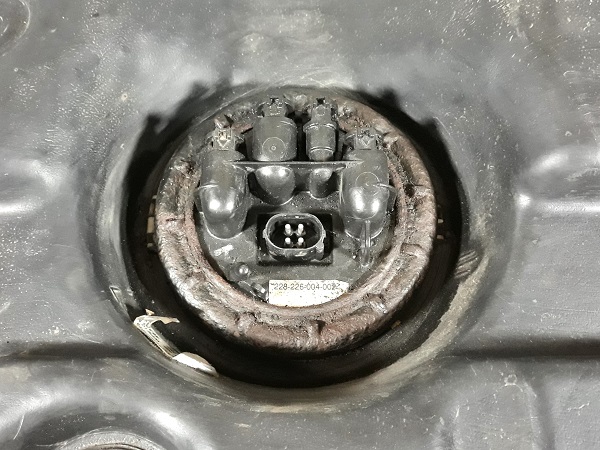
Locate the fuel pump power connector (3rd photo).
Op 02
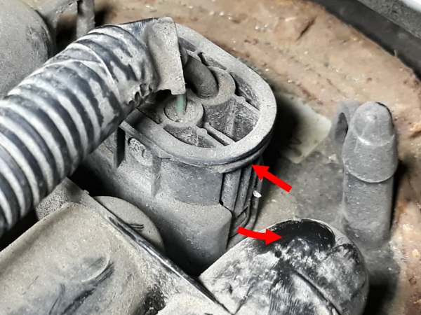
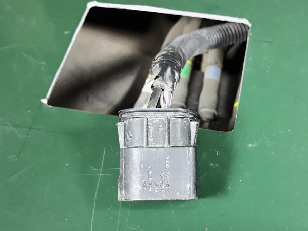
Disconnect the in-tank fuel pump power connector :
•
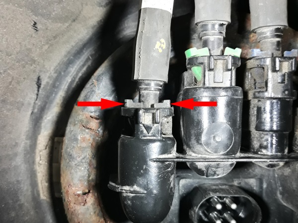
Unlock the 2 locking clips (1st photo). Press by hand or use pliers.
•
Pull the connector upwards.
Do not pull on the wires to disconnect the connector. Pull on the connector itself.
Finally, I don't know if I did well to use pliers because I broke the 2 locking clips.
Op 03
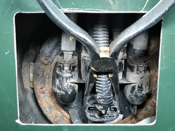
Note the position of each of the 4 fuel hoses connected to the in-tank pump.
If necessary, take a photo to be sure not to mix them up during reassembly.

Op 04
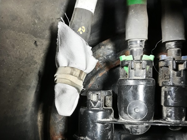
Disconnect a fuel hose :
•
Unlock the 2 locking clips (1st photo). Press by hand.
•
Pull the hose.
•
Plug the end of the hose. Use a clean cloth.
Always protect the hoses with cloths to prevent any impurities from entering the fuel system.
Op 05
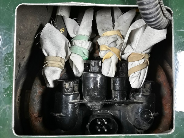
Disconnect and plug the 3 other fuel hoses. Proceed in the same way.
Op 06
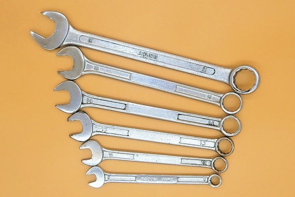
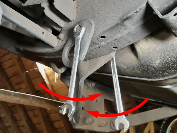
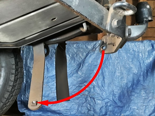
Unscrew the fixing bolts of the 2 reinforcement bars on the towing plate. Use the 15 mm spanner.
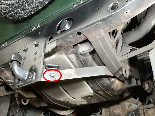
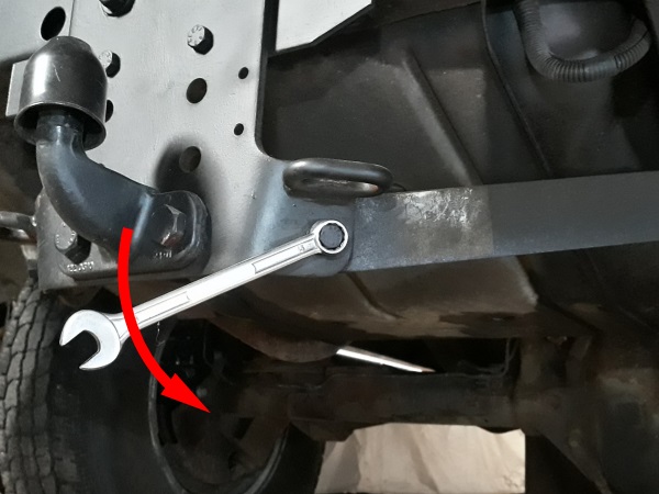
Op 07
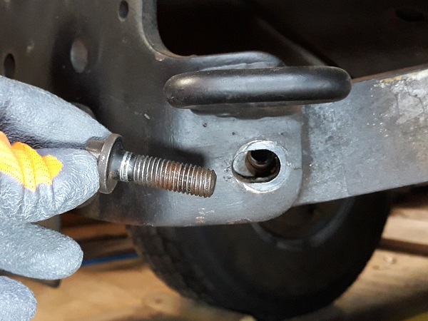
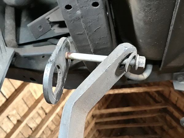
Unscrew the fixing bolts of the 2 towing plate reinforcement bars on the chassis. Use the 13 and 15 mm spanners.
Recover the reinforcement bars, towing rings, bolts, washers and nuts.
The reinforcement bars will pivot downwards when you loosen the fixing bolts. Be careful not to catch your fingers or head.
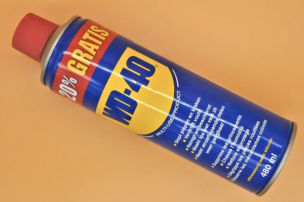
Do not hesitate to spray penetrating oil on the fixing bolts because they are very often oxidized.

Op 08
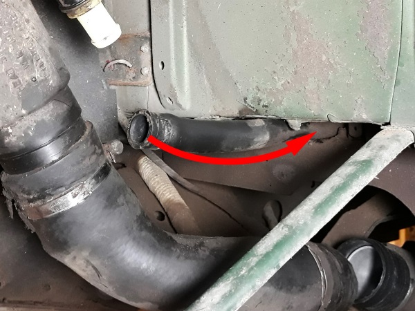
Loosen the filler neck hose clip on the tank. Use the multigrip pliers.
Detach the filler neck hose from the tank. Pull by hand.


Op 09
Loosen the breather hose clip on the filler neck. Use multigrip pliers.
Detach the breather hose from the filler neck. Pull by hand.
Recover the clip.


Op 10
Unclip the gooseneck of the vent hose from the 2 clips that hold it against the wheel arch. Pull by hand.
The vent hose is located under the left rear wheel arch.


Op 11
Unclip the vent hose from the clip that holds it to the rear of the chassis. Pull by hand.
This clip is very difficult to access because it is located at the rear of the chassis above the rear crossmember.


Op 12
Place a support under the tank cradle. Use a jack or wooden blocks.


Op 13
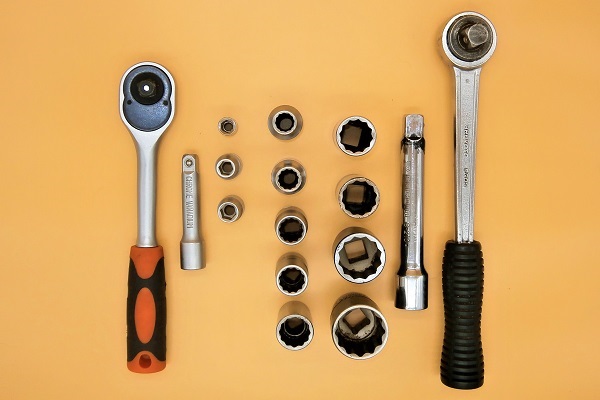
Unscrew the 2 rear fixing nuts of the tank cradle. Use the 15 mm socket.


Op 14
Unscrew the 2 front fixing bolts of the tank cradle. Use the 13 mm spanner.


Op 15
Remove the tank cradle :
•
Lower the front of the cradle.
•
Pull the cradle forward to disengage the rear mountings.
This is when you need someone to help. Ask a friend to hold the tank in place.


Op 16
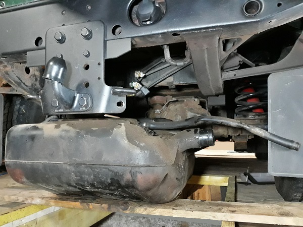
Lower the left side of the tank (1st photo).
Unclip the vent hose from the clip holding it to the chassis above the tank. Pull by hand.


Op 17
Release the vent hose.


Op 18
Release the breather hose.
Remove the fuel tank.
Advertisement
Change the in-tank fuel pump
Op 19
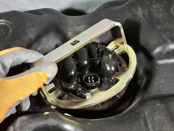
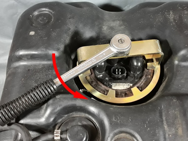
Thoroughly clean the area around the in-tank fuel pump.
Unscrew and remove the fuel pump locking ring. Use tool PM353 or tool DA1209.
When the locking ring is unscrewed, the pump will rise a few millimeters (4th photo).

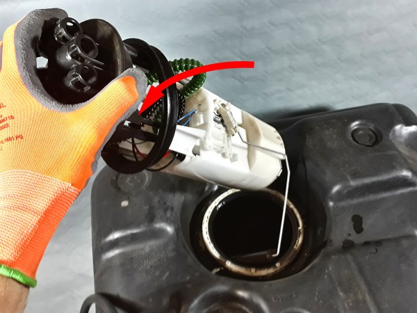
Op 20
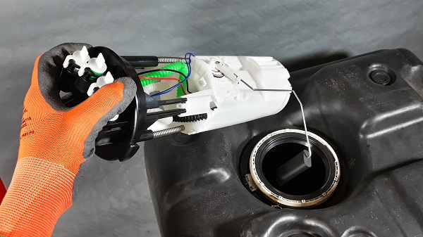
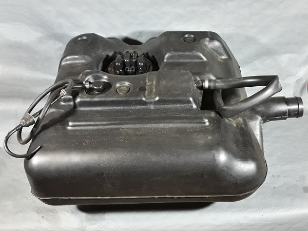
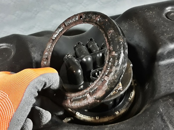
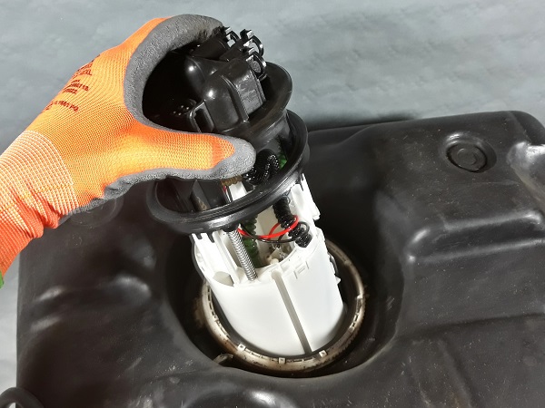
Remove the fuel pump. Pull upwards by hand.
When the pump body is out, rotate the pump slightly to the side to remove the gauge float (3rd photo).
Check that the seal has come off with the pump. If not, remove the seal remaining on the tank.

Op 21
Thoroughly clean the tank around the fuel pump port.
Now that the pump has been removed, take the opportunity to drain the tank and clean out any dirt that has accumulated at the bottom.

Op 22
Position the new fuel pump seal (WGQ500020) on the tank.
Lightly lubricate the lip of the seal with fuel (3rd photo).
A little fuel on the lip of the seal will make it easier to fit the pump.


Op 23
Engage the new fuel pump (WFX000260) in the tank.
The lower part of the pump will rest on the bottom of the tank and the upper part of the pump will protrude a few millimeters above the tank. This is normal. We will position it during the next Op.


Op 24
Rotate the pump to :
•
Place the fuel inlets/outlets towards the front of the tank.
•
Position the pump lug above the collar notch (2nd photo).


Op 25
Lower the upper part of the pump into the tank. Press by hand.
The upper part of the pump usually remains locked in position in the tank collar.


Op 26
Screw the locking ring onto the tank. Start by screwing the ring on by hand.
Tighten the ring. Use tool PM353 or tool DA1209.
Tighten firmly without damaging the locking ring lugs.


Change the hoses (if necessary)
Op 27
Check the tank breather hose.
As you saw during disassembly, the breather hose is compressed between the chassis and the body. It is often damaged. If so, replace it.

Op 28
Release the breather clip. Use a small flathead screwdriver.
Remove the breather hose. Pull by hand.


Op 29
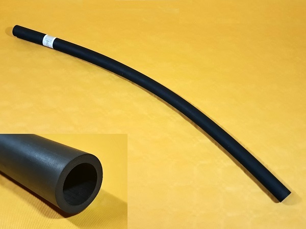
Place the clip (RTC3497) on the new breather hose (ESR4290).
Engage the hose on the tank.
The original breather hose is 55 cm long. Check that the length of the new hose is identical to the old one. If necessary, reduce the length of the new hose. Use a cutter.


Op 30
Lock the clip. Use multigrip pliers.


Op 31
Check the vent hose.
Change the vent hose if it is damaged.
Also take the opportunity to check that the vent hose is not obstructed.

Advertisement
Fit the tank
Op 32
Position the fuel tank on its cradle under the Defender.
The tank and its cradle have 2 longitudinal grooves. The tank is automatically centered on its cradle thanks to these grooves.

Op 33
Engage the breather hose between the chassis and the body.


Op 34
Pass the vent hose over the upper tank strap and then behind the chassis above the rear crossmember.


Op 35
Lift the rear part of the tank cradle.
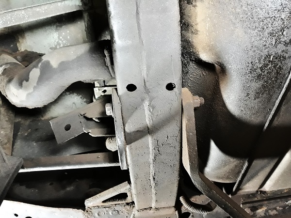
Engage the 2 cradle bolts (1st photo) in the 2 punch marks of the rear crossmember (2nd photo).
You can call your friend back. Their help will be very useful.
Apply a little copper grease on the thread of the fixing bolts. This will limit oxidation and make it easier to unscrew during the next disassembly.


Op 36
Clip the vent hose onto the clip (MXC1848) that holds it on the chassis above the tank. Press by hand.
You can access this clip by reaching through the chassis under the left rear wing (2nd photo).


Op 37
Clip the vent hose onto the clip (MXC1848) that holds it at the rear of the chassis. Press by hand.


Op 38
Check that the breather hose is in place and not pinched.


Op 39
Check the presence of the 2 tank protection rubbers on the chassis crossmember located at the front of the tank (2nd photo).


Op 40
Lift the front part of the tank cradle.

Op 41
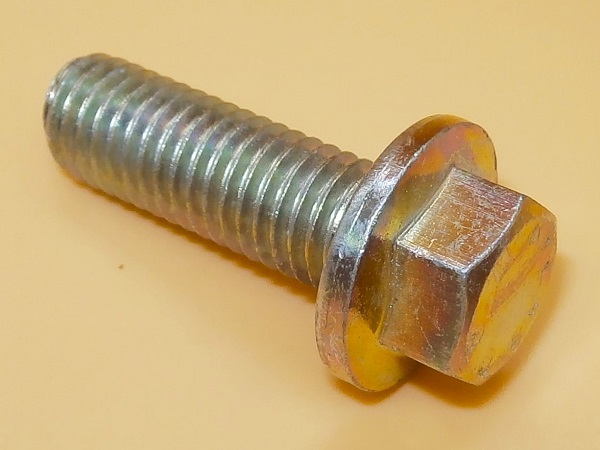
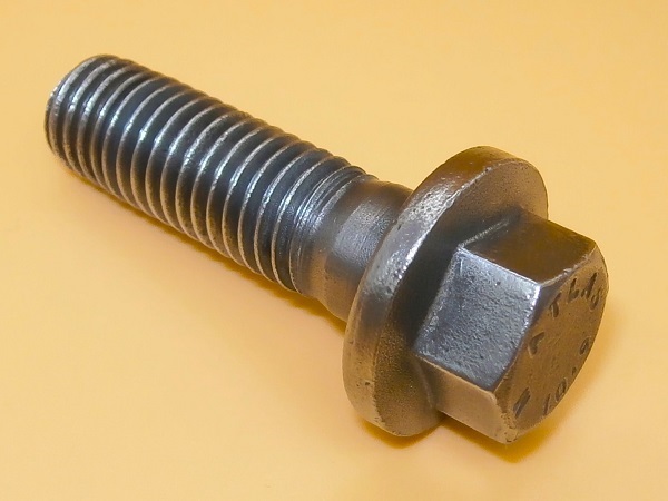
Screw in the 2 front tank cradle fixing bolts (FS110301L). Use the 13 mm spanner.
Tighten the 2 bolts to a torque of 25 mN. Use the 13 mm socket and the torque wrench.
Apply a little copper grease on the thread of the fixing bolts. This will limit oxidation and make it easier to unscrew during the next disassembly.


Op 42
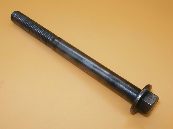
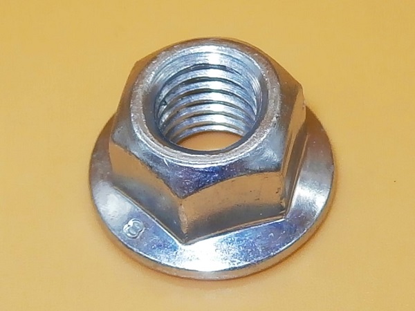
Screw in the 2 rear tank cradle fixing nuts (FY110057). Use the 15 mm socket.
Tighten the nuts to a torque of 25 mN. Use the torque wrench.


Op 43
Clip the gooseneck of the vent hose onto the 2 clips (MXC1848) that hold it against the wheel arch. Push by hand.
If the hose is not long enough to clip the gooseneck correctly, slide the hose at its first 2 clips (above the tank and rear of the chassis).


Op 44
Place the clip (RTC3497) on the breather hose.
Engage the breather hose on the filler neck. Push by hand.
Tighten the clip. Use the 7 mm shaped socket spanner.


Op 45
Check that the small aluminum tube is still present in the fuel tank inlet.
It remains to be confirmed but I imagine that this aluminum tube reinforces the tank inlet so that it does not collapse when tightening the hose clip.


Op 46
Place the clip (PYC102350) on the filler neck hose.
Engage the filler neck hose on the tank. Push by hand.
Tighten the clip. Use the 7 mm shaped socket spanner.


Op 47
Position the 2 towing rings on the chassis with the bolts (DYG000040).
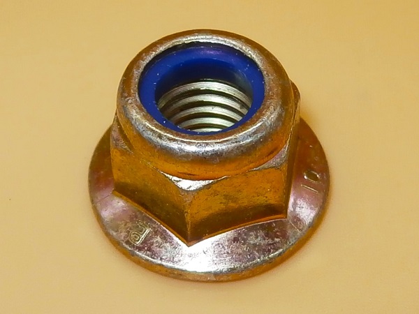
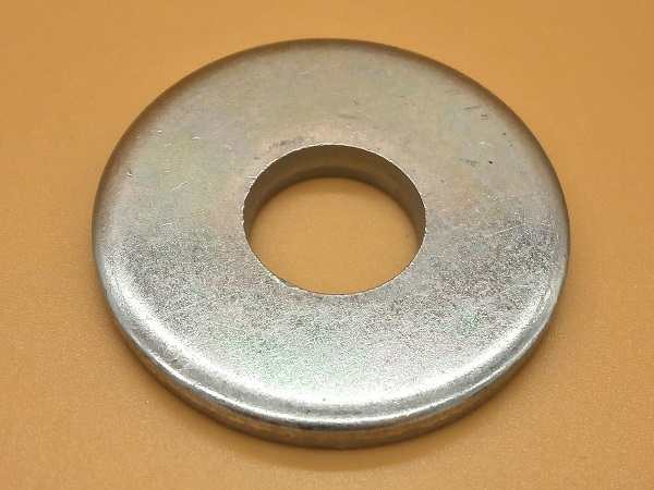
Position the towing plate reinforcement bars, the washers (KYF500070) and the nuts (FX110047L).
Apply a little copper grease on the thread of the fixing bolts. This will limit oxidation and make it easier to unscrew during the next disassembly.
Do not tighten the nuts for now.


Op 48
Position the reinforcement bars on the towing plate.
Screw in the fixing bolts (KYG500450).
Apply a little copper grease on the thread of the fixing bolts. This will limit oxidation and make it easier to unscrew during the next disassembly.


Op 49
Position the towing rings at the correct angle. They should be slightly oriented towards the rear of the Defender.
Tighten the fixing nuts. Use the 13 and 15 mm spanners.


Op 50
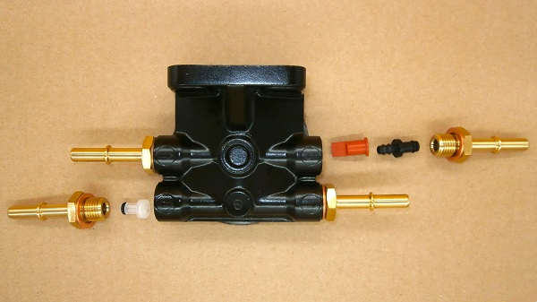
Remove one of the 4 plugs located on the new in-tank fuel pump. Use a small flathead screwdriver.
Start with the plug located to the LH of the pump.


Op 51
Remove the locking clip from one of the 4 fuel hoses. Use a small flathead screwdriver.
Start with the hose identified by a white sticker.


Op 52
Connect the hose to the fuel pump. Push by hand.
You will hear a click when the hose is properly locked.


Op 53
Connect the 3 other hoses to the fuel pump. Proceed in the same way.
Make sure to respect the order in which the hoses are connected (white, green, blue and black).

Op 54
Plug the connector onto the fuel pump. Push by hand.
The connector has a key (1st photo). It is impossible to connect it backwards.


Advertisement
Bleed the fuel system
Op 55
Bleed the fuel system (➔ see the tutorial ''Fuel filter change on Defender Td5'' Op 17).
Op 56
Start the engine.
Take a road test.
Fill the tank.
Check that there are no leaks at the fuel pump and filler neck.
The End