
This tutorial is also available in French
➔

Greasing propshafts on Defender 90 Td4
Vehicle ➔ Defender 90 Td4 2013
Difficulty ➔ Easy

Time ➔ 30 minutes
Summary
Advertisement
Advertisement

Recommendations

This tutorial concerns the Defender 90 Td4. The propshafts of the Defender 90 Td4 have only 2 grease nipples (on the universal joints). On this Defender, the body of the propshafts (telescopic part) does not have a grease nipple.
On the other hand, on the Defender 110 Td5, the propshafts have 3 grease nipples (on the universal joints and on the body of the propshaft).
On the other hand, on the Defender 110 Td5, the propshafts have 3 grease nipples (on the universal joints and on the body of the propshaft).
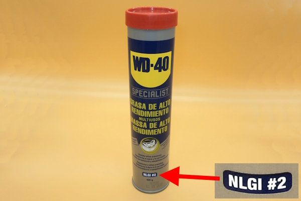
Grease recommended by Land Rover ➔ NLGI-2 universal lithium-based grease.
We grease the propshafts of our Defender every 5000 km.

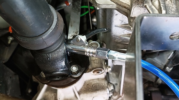
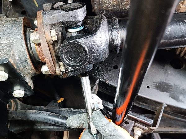
The grease nipples located on the propshafts universal joints are difficult to access and it is not always easy to position the grease gun coupler perfectly in line with the grease nipple. Result : a large part of the grease does not enter the grease nipple. It leaks at the coupler/nipple junction.
The prerequisites before connecting the grease gun coupler to the grease nipple are as follows :
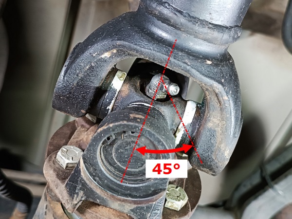
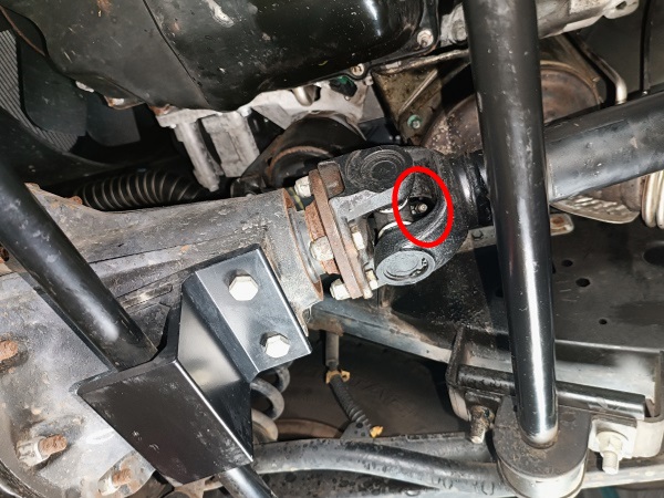
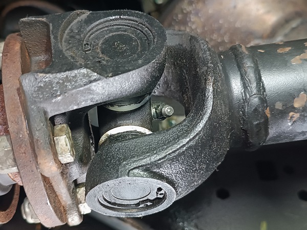
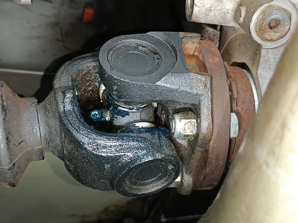
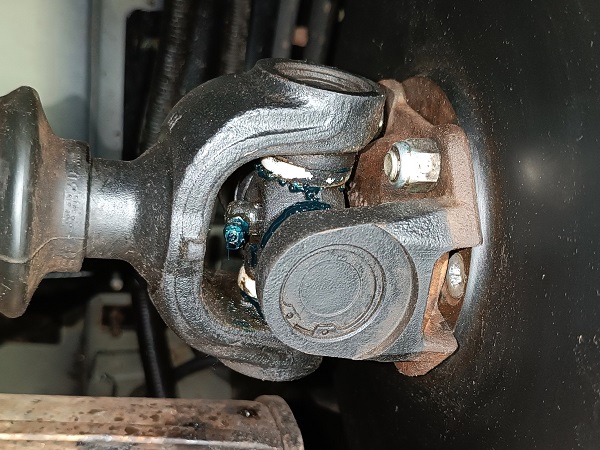
• The head of the grease nipple must be oriented at 45° relative to the trunnions of the universal joint (1st photo).
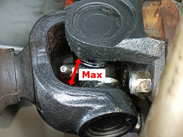
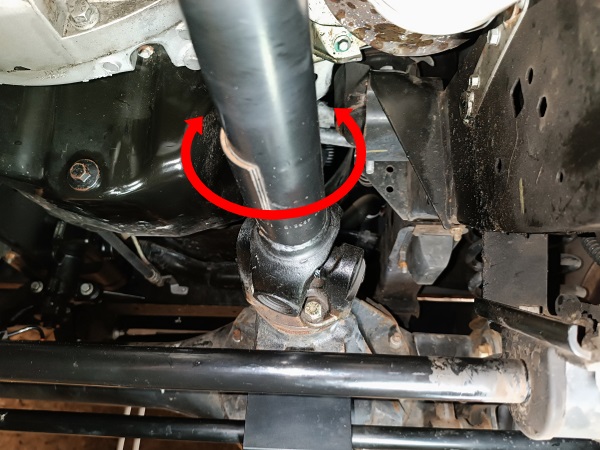
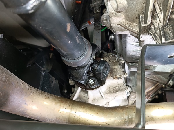
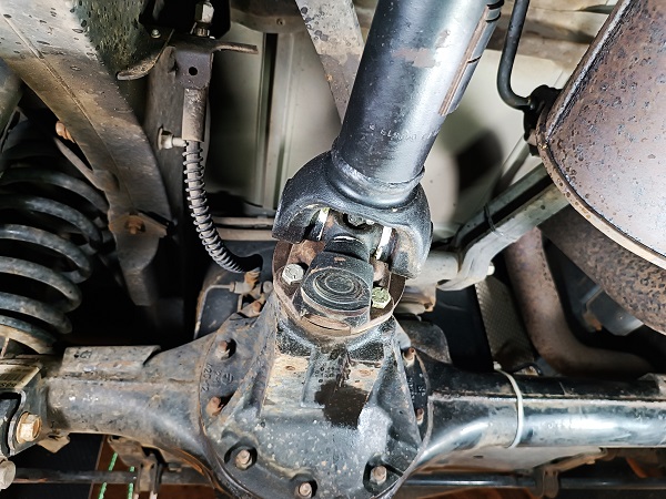
• The orientation of the propshaft must allow the widest possible access window to pass the coupler (2nd photo).
• The head of the grease nipple must be oriented at 45° relative to the trunnions of the universal joint (1st photo).
• The orientation of the propshaft must allow the widest possible access window to pass the coupler (2nd photo).
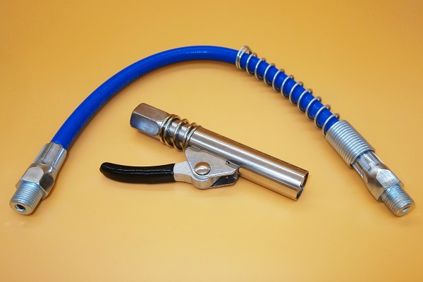
We invested a few euros in a reinforced locking grease gun coupler. This type of coupler strongly grips the head of the grease nipple and prevents any grease leakage. Thanks to it, greasing the propshafts is really easier and we no longer lose grease. Well, almost no more...
Required Tools
Sponsored links by

Advertisement
Grease the front propshaft
Op 01
Apply the handbrake.
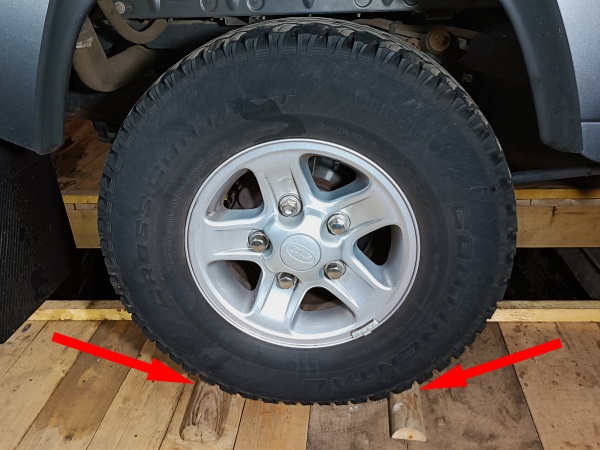
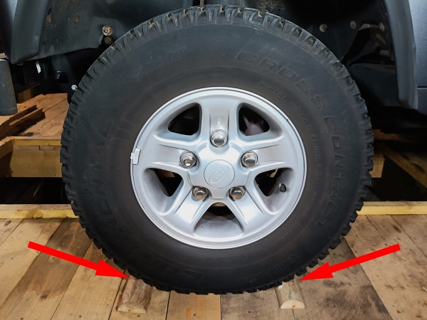
Immobilize the 2 rear wheels. Place wooden chocks.
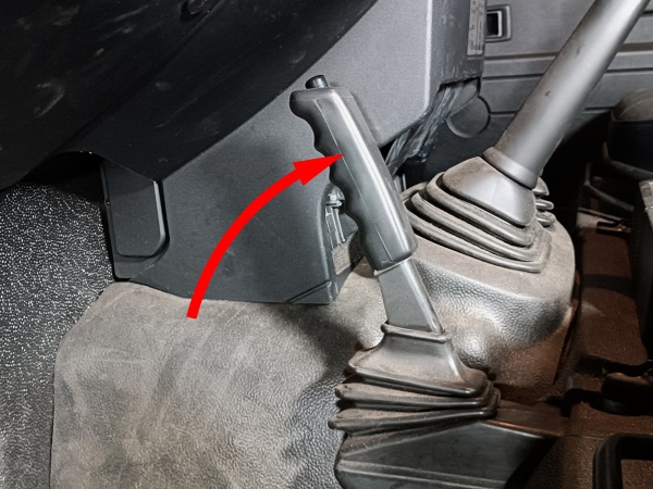
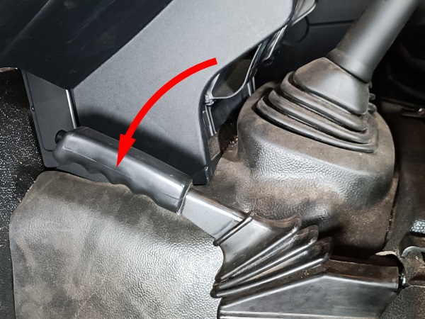
Put the gearbox in neutral.
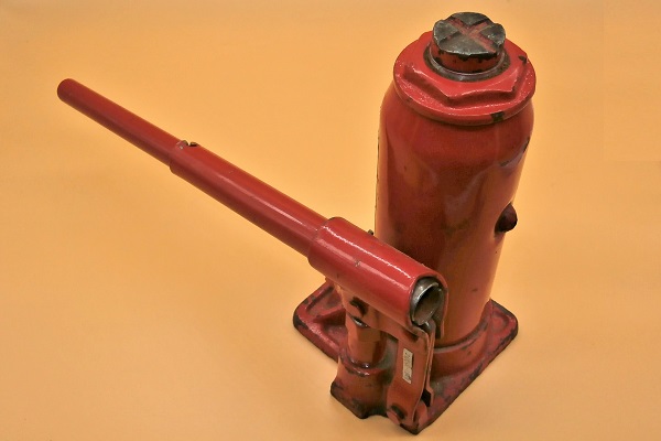
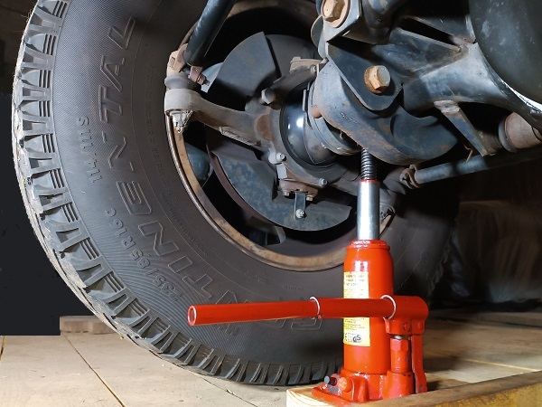
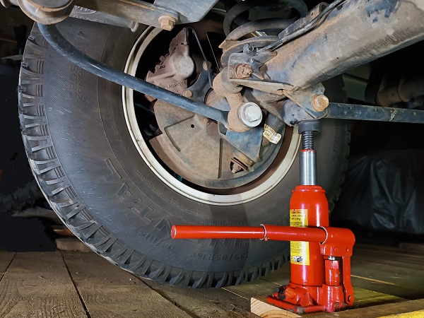
Raise a front wheel. Use the jack.
The wheel must no longer touch the ground so that you can rotate the propshaft during the following operations.
Op 02
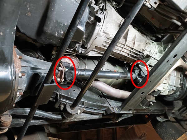
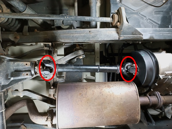
Identify where the 2 grease nipples are located on the front propshaft :
•
1 on the differential side.
•
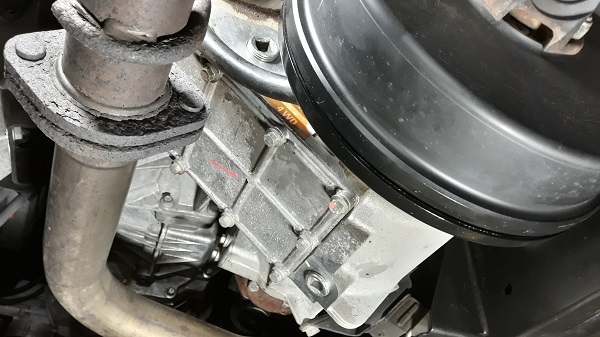
1 on the transfer box side.
The grease nipples are located at the universal joints. You will probably have to rotate the propshaft to see them appear.
Op 03
Orient the grease nipple on the differential side :
•
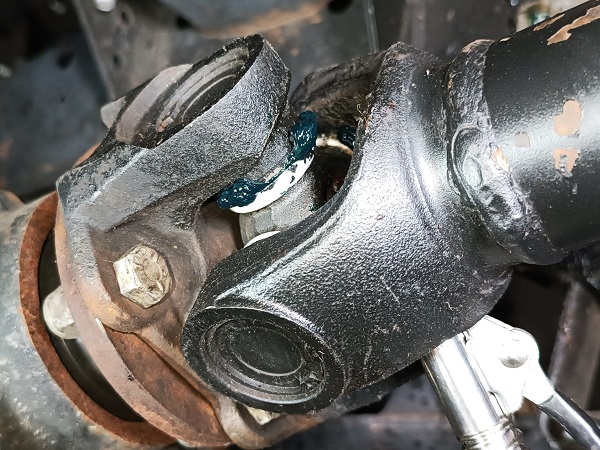
Check that the head of the grease nipple is well positioned at 45° relative to the trunnions of the universal joint.
•
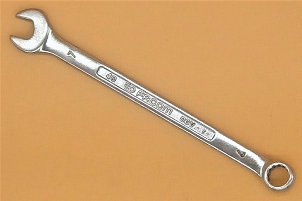
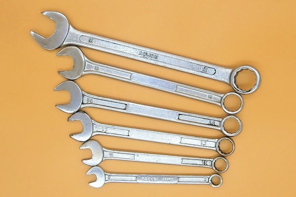
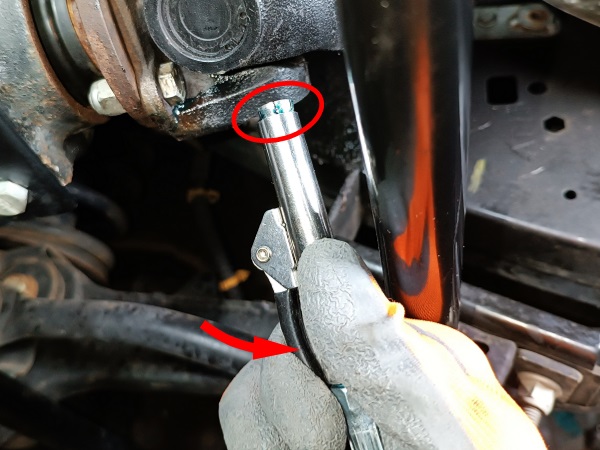
If necessary, slightly loosen the grease nipple and rotate it. Use the 11 mm combination spanner or the 7 mm combination spanner.
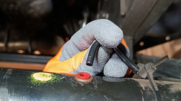
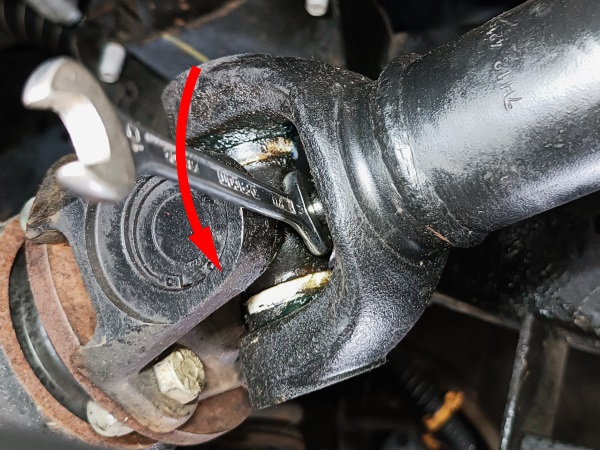
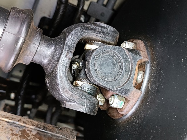
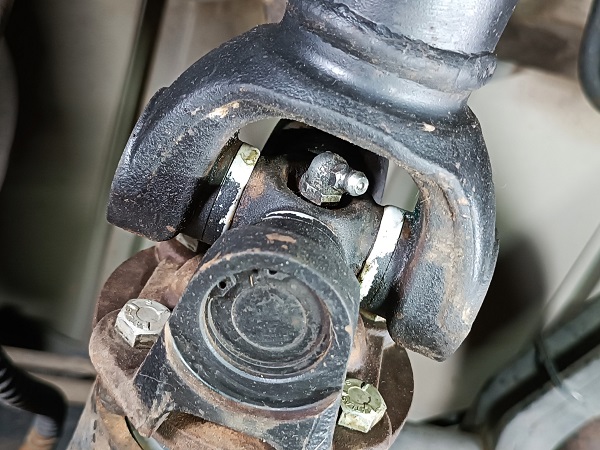
The grease nipple is normally screwed in with an 11 mm spanner (2nd photo). Unfortunately, the grease nipple is slightly recessed in a counterbore and is difficult to access with the 11 mm spanner.
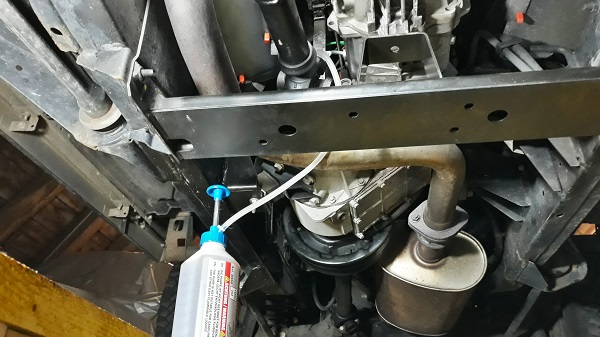
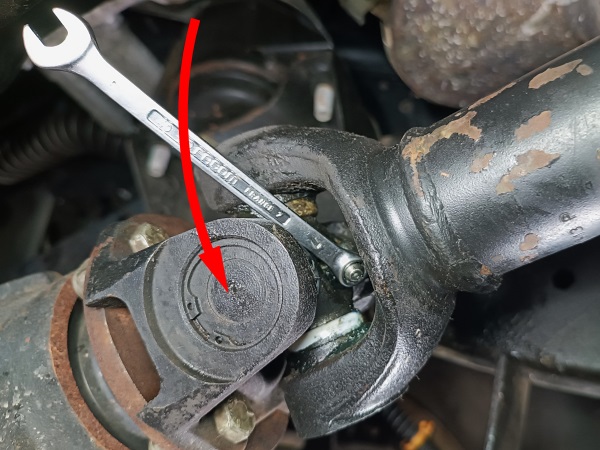
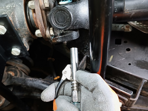
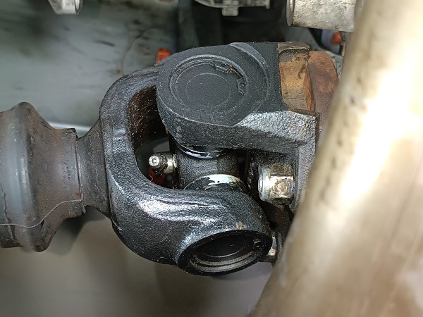
Another method is to use the 7 mm combination spanner (3rd photo). Simply engage the eye of the spanner on the head of the grease nipple and rotate it. It's not a very orthodox method but it works.
Op 04
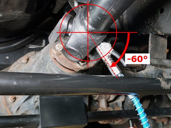
Position the propshaft to free the best access window to the grease nipple. Rotate the propshaft by hand.
For each of the 4 grease nipples, there is a propshaft orientation that frees the widest access window for the passage of the grease gun coupler.
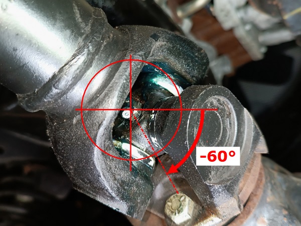
The grease nipple must be oriented with approximately an angle of -60° relative to the horizontal (3rd photo).
Op 05
Connect the grease gun coupler to the grease nipple :
•
Clean the grease nipple. Use a cloth.
•
Open the locking jaws of the coupler (2nd photo). Actuate the lever by hand.
•
Engage the coupler on the grease nipple. Push hard.
•
Release the lever.
Op 06
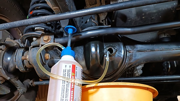
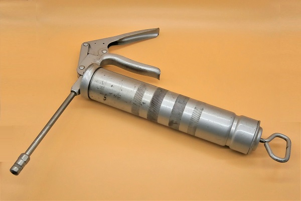
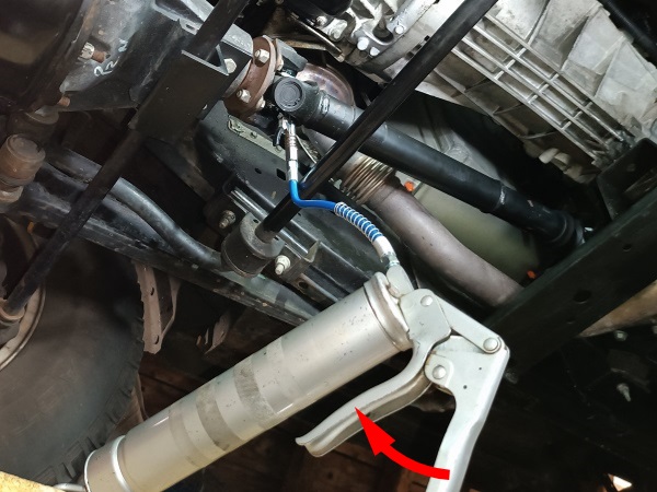
Inject grease into the grease nipple. Pump by hand.
Remove the grease gun coupler.
When you pump, check that there is no grease leaking between the grease gun coupler and the grease nipple. If it leaks, improve the position of the coupler.
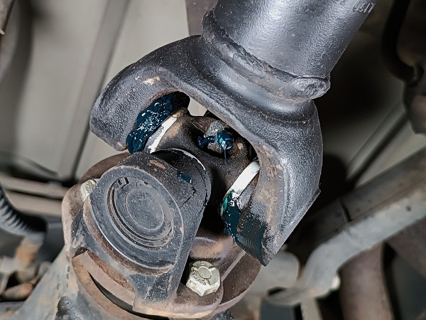
Inject grease until it comes out slightly at each of the 4 trunnions of the universal joint (2nd photo).
Op 07
Retighten the grease nipple. Use the 11 mm combination spanner or the 7 mm combination spanner.

Op 08
Grease the universal joint on the transfer box side. Repeat Op 03 to 07.
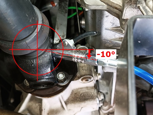
The head of this grease nipple must be oriented with approximately an angle of -10° relative to the horizontal (3rd photo).
Advertisement
Grease the rear propshaft
Op 09
Immobilize the front wheels. Place wooden chocks.
Release the handbrake.
Raise a rear wheel. Use the jack
Op 10
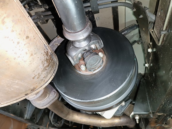
Identify where the 2 grease nipples are located on the rear propshaft :
•
1 on the transfer box side.
•
1 on the differential side.
Op 11
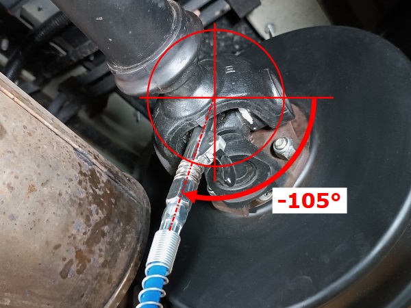
Grease the universal joint on the transfer box side. Repeat Op 03 to 07.
The head of this grease nipple must be oriented with approximately an angle of -105° relative to the horizontal (3rd photo).
Op 12
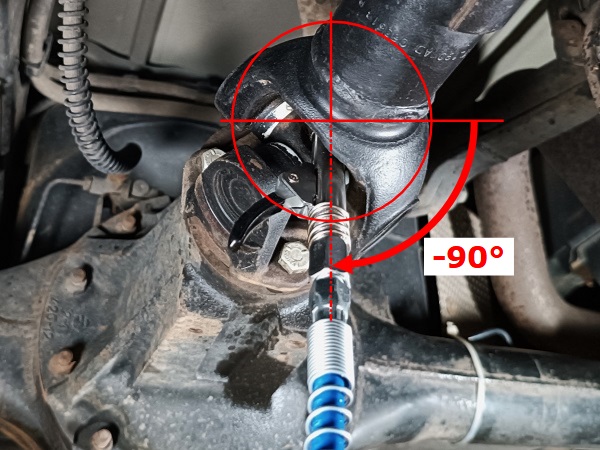
Grease the universal joint on the rear differential side. Repeat Op 03 to 07.
The head of this grease nipple must be oriented with approximately an angle of -90° relative to the horizontal (3rd photo).
The End