
This tutorial is also available in French
➔

Injectors seals change on Defender Td5
Vehicle ➔ Defender 110 Td5 2002
Difficulty ➔ Medium

Time ➔ 3 hours
Summary
Advertisement
Advertisement

Recommendations

Is your Defender Td5 having trouble starting ? When starting, does the in-tank fuel pump make a high-pitched noise because the fuel system has lost its prime ? This is probably due to the injector seals failing.

Each injector is equipped with an O-ring and a sealing washer. Do not hesitate to invest in very high quality seals.
Do not swap the injectors. Each injector is programmed at the ECU level to be on one of the 5 cylinders. If you swap the injectors, the Defender will no longer start.
The workshop manual recommends that the rocker arm adjustment screws and nuts, as well as the rocker shaft fixing bolts, should always be replaced. We have not followed this recommendation. We reused them.
The injector puller
There are several methods for removing the injectors :
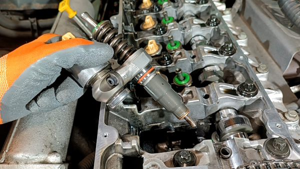
• The workshop manual recommends using the specific tool LRT-12-154/1 (1st photo). This tool consists of 2 half-shells perfectly adapted to the Td5 injector and a slide hammer. The extraction is done perfectly in the axis of the injector. To avoid any risk of damaging the injectors or the cylinder head, we preferred to invest in this tool.
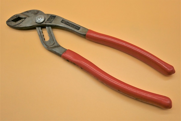
• Some Land Rover enthusiasts simply lever with modified multigrip pliers (2nd photo). This tip avoids investing in a relatively expensive injector puller.
• The workshop manual recommends using the specific tool LRT-12-154/1 (1st photo). This tool consists of 2 half-shells perfectly adapted to the Td5 injector and a slide hammer. The extraction is done perfectly in the axis of the injector. To avoid any risk of damaging the injectors or the cylinder head, we preferred to invest in this tool.
• Some Land Rover enthusiasts simply lever with modified multigrip pliers (2nd photo). This tip avoids investing in a relatively expensive injector puller.


The LRT-12-154/1 injector puller is manufactured by 2 companies :
• Laser Tools ➔ ref 7166. This tool is sold by most Land Rover parts dealers.
• Sealey ➔ ref VS2541. This tool is sold by Amazon and eBay (among others). It is much less expensive.
• Laser Tools ➔ ref 7166. This tool is sold by most Land Rover parts dealers.
• Sealey ➔ ref VS2541. This tool is sold by Amazon and eBay (among others). It is much less expensive.
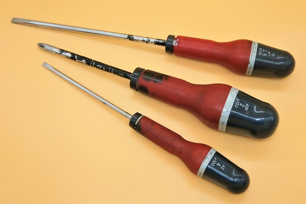
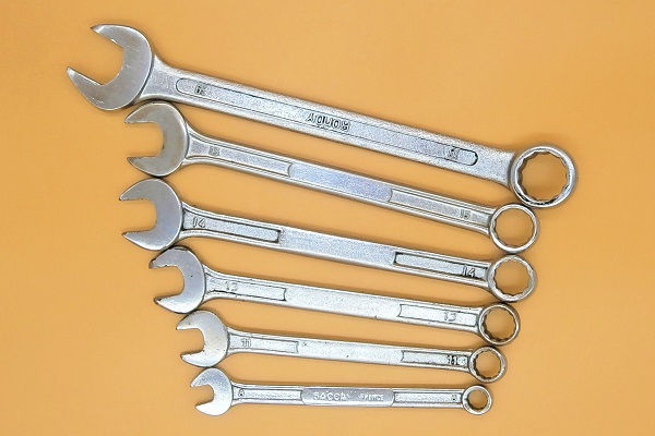
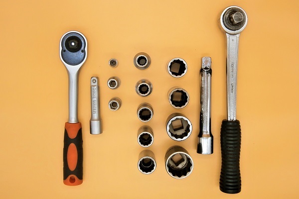
Required Tools
Sponsored links by


Spare Parts
Our Partner


Packaging :
•
The above parts are sold individually.
• ERR6417 and ERR7004 : The injector sealing washers and O-rings are sold individually but there is also the DA2479G kit containing the 5 sealing washers and the 5 O-rings.
• ERR6417 and ERR7004 : The injector sealing washers and O-rings are sold individually but there is also the DA2479G kit containing the 5 sealing washers and the 5 O-rings.
Advertisement
Remove the acoustic cover
Op 01
Remove the acoustic cover (➔ see the tutorial ''Engine oil change on Defender Td5'' Op 05 to 07).
Remove the viscous fan
Op 02
Remove the viscous fan (➔ see the tutorial ''Viscous fan change on Defender Td5'' Op 02 to 07).
Removing the fan will allow us to access the crankshaft pulley. We will be able to turn the crankshaft using a 24 mm socket during the following operations.
Remove the injectors harness
Op 03
Remove the injectors harness (➔ see the tutorial ''Injectors harness change on Defender Td5'' Op 02 to 14).
Remove the rocker & arm assy
Op 04
Locate the crankshaft pulley and position the 24 mm socket on its nut.


Op 05
Turn the crankshaft until the camshaft sprocket mark (small line) is in the high position and located in the center of the 2 colored links of the timing chain (2nd photo). Use a 24 mm socket.
Let's remember the obvious : when you turn the crankshaft, you also turn the camshaft.
Turn the crankshaft clockwise.
If the camshaft sprocket mark is in the high position but the 2 colored links of the chain are not positioned on either side of this mark, it is not good (3rd photo). If this is the case, turn the crankshaft one more turn.
This manipulation positions the piston of cylinder #1 at its top dead center. Cylinder #1 is the one closest to the camshaft pulley.
To be honest, I don't know if this angular positioning of the camshaft is really essential to remove the rocker shaft, but it is recommended in the workshop manual. So we carried out this operation.


Op 06
Look at the camshaft just at the pulley. You will discover a groove machined in the camshaft.
This groove allows the LRT-12-058 tool to be positioned to immobilize the camshaft in rotation.


Op 07
Immobilize the camshaft in this position. Use the LRT-12-058 tool.


Op 08
Release the stresses on the 5 rocker arms :
•
Loosen the 5 rocker arm adjuster nuts. Use a 13 mm spanner.
•
Loosen the 5 adjustment screws. Use a flathead screwdriver.
The stresses on the rocker arms must be reduced as much as possible to avoid any risk of damage during the removal and reassembly of the rocker shaft.


Op 09
Gradually unscrew the 6 rocker shaft fixing bolts. Use a 10 mm socket.
It is preferable to loosen the 6 bolts gradually in a spiral pattern. This avoids deforming the rocker shaft.
During removal, loosening the bolts in a spiral pattern is done starting from the outside to the inside (2nd photo). Start with the bolt farthest from the center of the part and finish with the bolt closest to the center.
Leave the 6 fixing bolts on the rocker shaft. If you have decided to reuse them, it is preferable not to swap them during reassembly.


Op 10
Remove the rocker & arm assy. Lift it by hand.


Op 11
Remove the camshaft locking tool (LRT-12-058). Pull by hand.


Change the injectors seals
Op 12
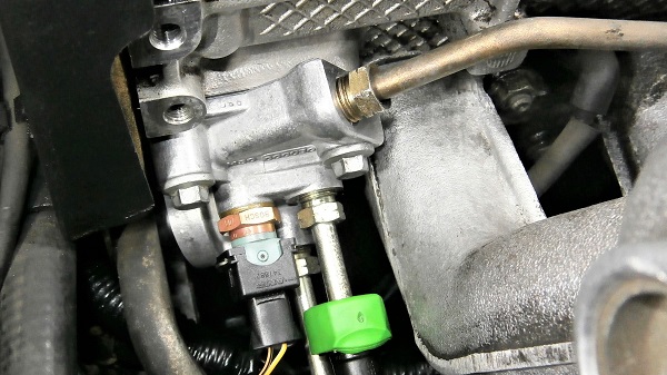
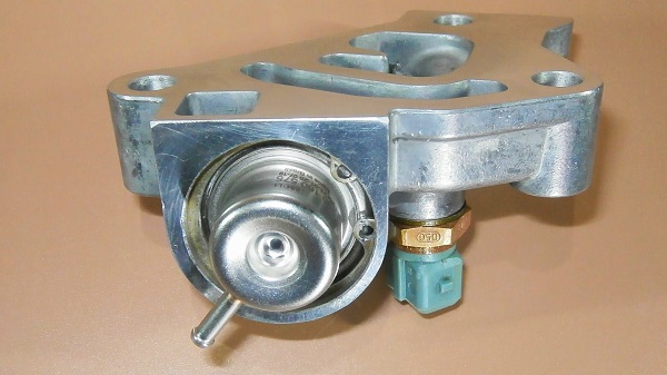
Disconnect the fuel supply hose from the fuel pressure regulator :
•
Move the green cover away.
•
Press the 2 locking tabs with your fingers.
•
Detach the fuel supply hose. Pull by hand.
Position a drain pan under the engine because some fuel will flow out.


Op 13
Disconnect the fuel cooler hose :
•
Slide the black collar towards the hose. Use a flathead screwdriver.
•
Detach the hose. Pull by hand.
This operation is delicate because the hose connector is hidden behind the fuel cooler.
The movements must be broken down : first slide the black collar without pulling on the hose (this releases the locking mechanism) and when the mechanism is unlocked, pull on the hose to disconnect it.


Op 14
Unlock injector #1 :
•
Unscrew the fixing bolt. Use a 10 mm socket.
•
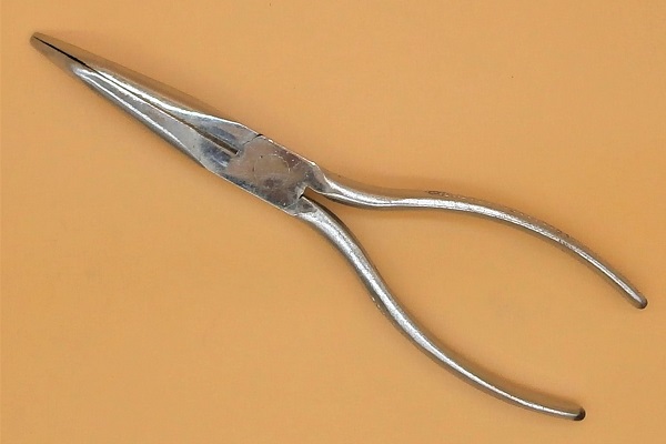
Remove the fixing bolt. Use needle-nose pliers.
•
Remove the retaining clamp. Use needle-nose pliers.


Op 15
Rotate the camshaft to free up access to injector #1. Use a 24 mm socket to turn the crankshaft.
Depending on the angular position of the camshaft, the cam may prevent the injector puller from being fitted (1st photo). Simply rotate the camshaft a few degrees to free up access (2nd photo).


Op 16
Position the 2 half-shells of the puller (Sealey VS2541) on either side of injector #1.


Op 17
Complete the assembly of the puller (Sealey VS2541) :
•
Place the slide hammer rod between the two half-shells. The 14 mm nut should be between the half-shells and the 19 mm nut should be on top (1st photo).
•
Place the locking ring on the half-shells (2nd and 3rd photos).
•
Tighten the nut on the slide hammer rod (5th photo). Use 8 mm and 19 mm spanners.
There are 2 flats on the slide hammer rod (4th photo). These flats allow the rod to be held in place during tightening (with an 8 mm spanner).


Op 18
Remove the injector. Use back and forth movements with the slide hammer.
Handle the slide hammer perfectly in line with the injector.


Op 19
Remove the sealing washer from the injector. Use the multigrip pliers.
Position the pliers only on the washer and not on the injector body. Be careful not to mark the injector.
The injector nozzle is sometimes dirty and prevents the washer from being removed. If this is the case, clean the injector nozzle with a cloth before removing the washer.


Op 20
Remove the O-ring from the injector. Use a small flathead screwdriver.


Op 21
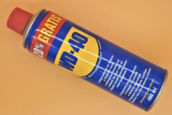
Clean the injector nozzle. Use a cloth and WD40.
Do not use a wire brush to clean the injector nozzle.


Op 22
Position the new O-ring (ERR7004) on the injector :
•
Lubricate the entire injector stem with engine oil.
•
Lubricate the seal with engine oil.
•
Position the seal on the injector.
•
Check that the O-ring is in position and not twisted.
Lubricating the injector stem and O-ring will make it easier to fit the seal and prevent it from twisting.


Op 23
Position the new sealing washer (ERR6417) on the injector.


Op 24
Fit the injector on the cylinder head :
•
Thoroughly clean the injector housing. Use a cloth.
•
Check for the presence of the injector clamp positioning pin (2nd photo).
•
Engage the injector in its housing. Push by hand.


Op 25
Fit the injector retaining clamp. Use needle-nose pliers.
Check that the back of the clamp is correctly positioned on its positioning pin (3rd photo).


Op 26
Fit the injector fixing bolt (MBD100050) :
•
Start screwing in the bolt by hand to avoid stripping the thread.
•
Tighten the bolt to a torque of 32 Nm. Use a 10 mm socket and a torque wrench.


Op 27
Change the seals on the other 4 injectors. Proceed in the same way (Op 14 to 26).

Op 28
Connect the hose to the fuel cooler. Push by hand.


Op 29
Connect the fuel supply hose to the rigid fuel pipe of the fuel pressure regulator :
•
Connect the hose. Push by hand.
•
Slide the green cover onto the connector. Push by hand.


Fit the rocker & arm assy and adjust the rocker arms
Op 30
Place the camshaft back in position and immobilize it with tool LRT-12-058 (same as Op 05 to 07).


Op 31
Position the rocker & arm assy :
•
Clean the rocker & arm assy thoroughly.
•
Place the rocker & arm assy on the cylinder head.
•
Engage the rocker shaft on the centering pin (2nd photo).
•
Check that the rocker arms are correctly positioned. The adjustment screws of the 5 rocker arms must be above the injectors (4th photo).


Op 32
Tighten the 6 rocker shaft fixing bolts (LYG101510) :
•
Start screwing in the bolts by hand to avoid stripping the threads.
•
Slightly tighten the bolts. Use a 10 mm socket.
•
Gradually tighten the bolts to a torque of 32 Nm. Use a 10 mm socket and a torque wrench.
It is preferable to tighten the 6 bolts gradually in a spiral pattern. This avoids deforming the rocker shaft.
During reassembly, tightening the bolts in a spiral pattern is done starting from the inside to the outside (2nd photo). Start with the bolt closest to the center of the part and finish with the bolt farthest away.


Op 33
Remove the camshaft locking tool (LRT-12-058). Pull by hand.

Op 34
Position the cam of injector #1 at maximum extension. Use a 24 mm socket to turn the crankshaft.
Turn the crankshaft clockwise.
Injector #1 is the one closest to the camshaft pulley.


Op 35
Look again at the camshaft just at the pulley. You will see the number 1 and a line engraved on the camshaft.
This number 1 and this line indicate that the cam of injector #1 is at maximum extension.
The line should be placed at the boss of the cylinder head (2nd photo).


Op 36
Adjust the rocker arm of injector #1 :
•
Tighten the rocker arm adjuster screw (LGV000020) until the injector plunger reaches its stop. Use a flathead screwdriver.
•
Loosen the same screw by one turn.
Loosening the screw by one turn prevents the injector piston from reaching its stop during engine operation. This clearance is necessary for the correct operation of the injector.


Op 37
Tighten the rocker arm adjuster nut (ERR5529) of injector #1 :
•
Screw in the nut while holding the adjuster screw in place. Use a 13 mm spanner and a flathead screwdriver.
•
Tighten the nut to a torque of 16 Nm. Use a 13 mm socket and a torque wrench.
Note the position of the screw slot before tightening the nut and check that it has not moved during tightening.


Op 38
Adjust the rocker arms of the other 4 injectors. Proceed in the same way (Op 34 to 37).
Of course, for each rocker arm you adjust, you will see the corresponding number engraved on the camshaft (2nd photo).


Op 39
Slowly turn the crankshaft 2 turns by hand. Use a 24 mm socket.
This will allow you to check that none of the 5 injectors are bottoming out and that nothing is blocking. Two precautions are better than one.

Fit the injectors harness
Op 40
Fit the injectors harness (➔ see the tutorial ''Injectors harness change on Defender Td5'' Op 15 to 28).
If you detect the slightest trace of oil at the red connector of the ECU
(➔ see the tutorial ''Check for oil in the ECU connector on Defender Td5''),
do not hesitate, systematically install a new injectors harness.
Advertisement
Fit the viscous fan
Op 41
Fit the viscous fan (➔ see the tutorial ''Viscous fan change on Defender Td5'' Op 08 to 10).
Bleed the fuel system
Op 42
Bleed the fuel system :
•
Place the ignition key in position 2.
•
Listen to the sound of the fuel pump (it will be higher pitched than usual).
•
Leave the key in position 2 for a few seconds while the sound of the pump returns to normal or it stops.
•
Turn off the ignition.
•
Repeat this operation 3 or 4 times.
•
Press the accelerator pedal to 90% of its travel.
•
Start the engine while holding the accelerator pedal down.
•
As soon as the engine starts, release the accelerator pedal.
Every time the fuel system has been opened and air has entered, it must be bled before starting the engine.
This time, we performed a more thorough purge of the fuel system than during a simple fuel filter change. We added an action : accelerator pedal pressed 90% when starting the engine. This additional action is necessary because we emptied the fuel system down to the injectors.


Drain the engine oil
Op 43
Drain the engine oil and change the oil filters (➔ see the tutorial ''Engine oil change on Defender Td5'').
If the injector seals were faulty, it is likely that fuel has mixed with the engine oil. If this is the case, the engine will no longer be properly lubricated. This is why it is preferable to always perform an engine oil change and change the 2 oil filters quickly after changing the injector seals.
The End