
This tutorial is also available in French
➔

Front wheel bearings change on Austin Mini
Vehicle ➔ Mini 1000 year 1988
Difficulty ➔ Medium
Time ➔ 3 hours
Summary
Advertisement
Advertisement

Recommendations

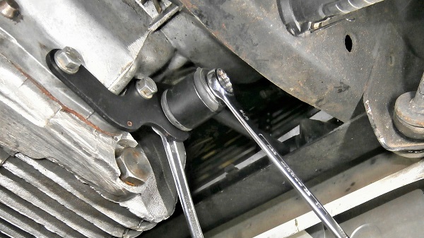
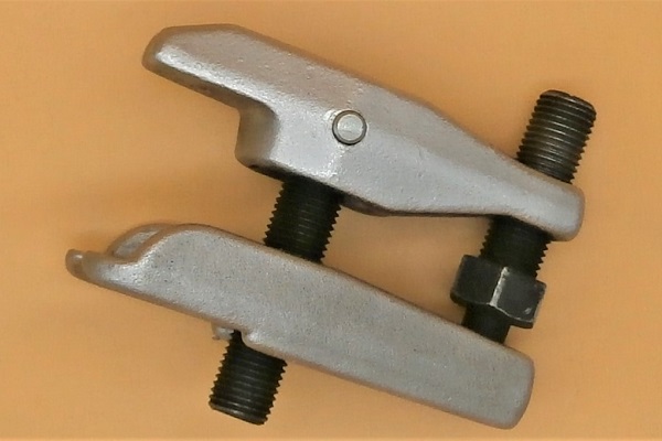
Use a very good quality ball joint puller to remove the track rod end and the ball joint because the force required is very important. If you break your ball joint puller, do not hesitate to invest in a better quality tool.
A bearing seal removed with a screwdriver is usually damaged. Provide a new seal before each disassembly.

Bearings are pre-adjusted assemblies. In the packaging, the rings and rollers of each bearing are either connected by a plastic link or in a plastic bag. Never mix the elements of one bearing with the elements of another. This could impair their operation.
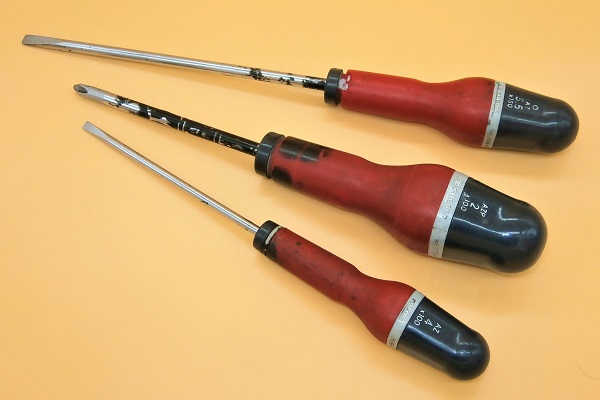
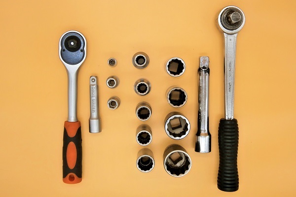
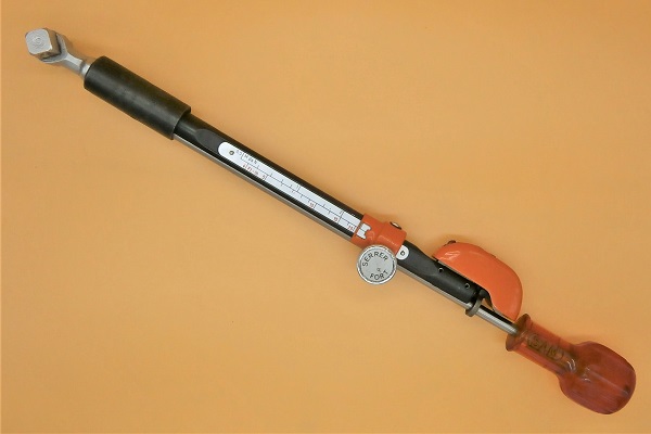
Required Tools
Sponsored links by

Spare Parts
Our Partners


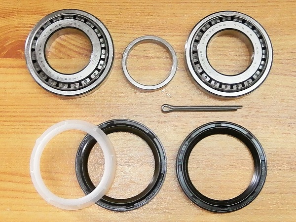
Packaging :
•
GHK1140 : Bearing kit for one wheel (2 bearings + 1 spacer + 2 seals + 1 water shield + 1 split pin). This kit can only be fitted on swivel hubs with disc brakes.
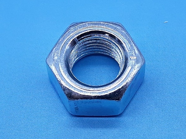
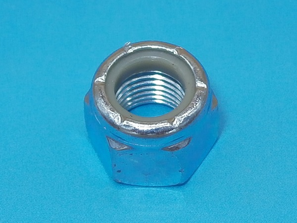
• The nuts and washers above are sold individually.
• The nuts and washers above are sold individually.
Advertisement
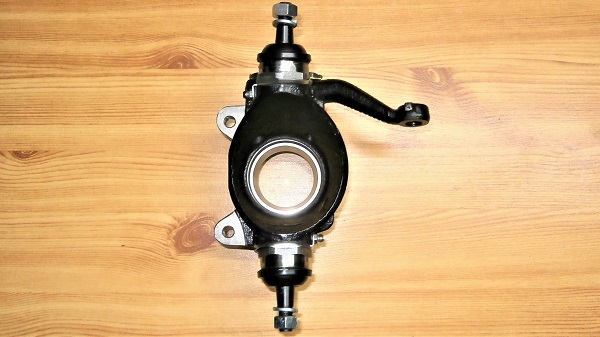
Remove the swivel hub
Op 01
Remove the wheel and the brake pads (➔ see the tutorial ''Front brake pads change'' Op 01 to 06).
Op 02
Remove the caliper, the brake disc and the drive flange (➔ see the tutorial ''Front brake discs change'' Op 02 to 07).
Op 03
Remove the swivel hub (➔ see the tutorial ''Swivel hub ball joints change'' Op 03 à 11).
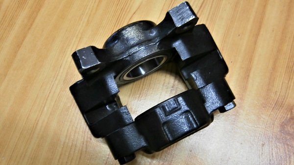
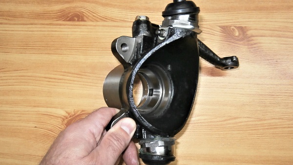
Remove the bearings
Op 04
Remove the outer seal. Use the flathead screwdriver.
The screwdriver must be long enough to have sufficient leverage.


Op 05
Remove the inner ring of the outer bearing (with its roller cage).

Op 06
Remove the inner seal. Use the flathead screwdriver.


Op 07
Remove the inner seal spacer.

Op 08
Remove the inner ring of the inner bearing (with its roller cage).

Op 09
Remove the bearing spacer.

Op 10
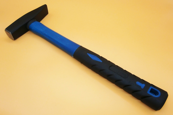
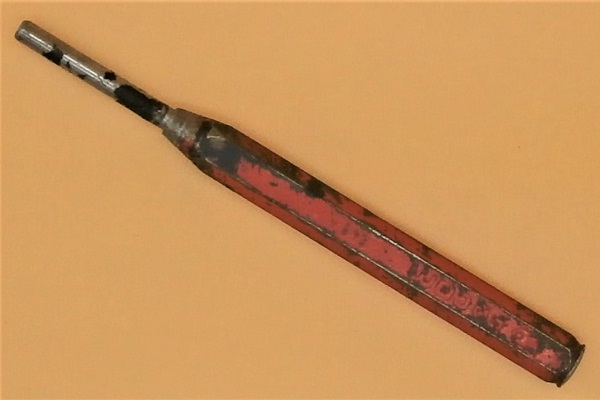
Remove the outer ring of the outer bearing. Use the pin punch and hammer.


Op 11
Remove the outer ring of the inner bearing. Use the pin punch and hammer.


Advertisement
Fit the bearings
Op 12
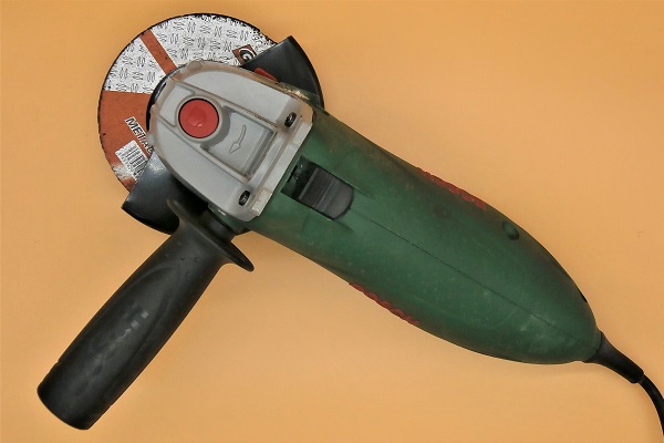
Cut the 2 old outer bearing rings. Use the grinder.
These rings will be used to position the outer rings of the new bearings. This method can be used if you do not have a hydraulic press.


Op 13
Fit the outer ring of the new outer bearing (kit GHK1140).
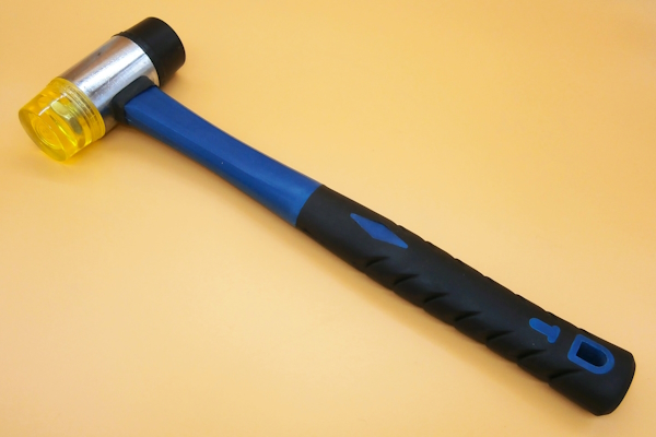
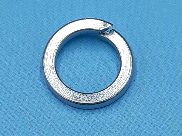
Drive the ring in deeply. Use an old cut ring and a mallet.
Once the new ring is in place, the cut ring can be removed very easily by hand.


Op 14
Fit the outer ring of the new inner bearing (kit GHK1140).
Use the 2 old cut rings because this new ring is driven in more deeply.


Op 15
Fit the inner ring of the outer bearing (with its roller cage).
Grease the bearing abundantly.


Op 16
Fit the outer seal (kit GHK1140). The seal goes in easily by hand.
Pack grease into the space between the bearing and the seal.
The seal should be flush with the end of the swivel hub.


Op 17
Fit the bearing spacer (kit GHK1140).


Op 18
Fit the inner ring of the inner bearing (with its roller cage).
Grease the bearing abundantly.


Op 19
Fit the inner seal spacer (kit GHK1140).


Op 20
Fit the inner seal (kit GHK1140).
Pack grease into the space between the bearing and the seal.
A tip for identifying the inner seal : it has a lip on its outer face.
The seal must bear against the spacer.
You can use a cut ring and the mallet again to drive in the seal.


Advertisement
Fit the swivel hub
Op 21
Fit the swivel hub (➔ voir le tuto ''Front brake pads change'' Op 41 à 47).
Op 22
Fit the drive flange, the brake disc and the caliper (➔ see the tutorial ''Front brake discs change'' Op 12 to 18).
Op 23
Fit the brake pads and the wheel (➔ see the tutorial ''Front brake pads change'' Op 10 to 16).
The End