
This tutorial is also available in French
➔

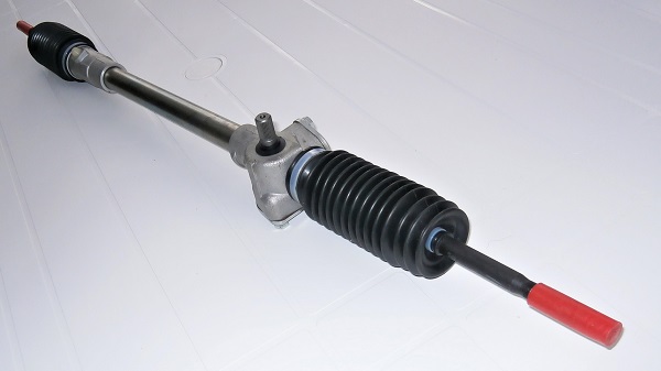
Steering rack change on Austin Mini
Vehicle ➔ Mini 1000 year 1988
Difficulty ➔ Medium
Time ➔ 10 hours
Summary
Advertisement
Advertisement

Recommendations

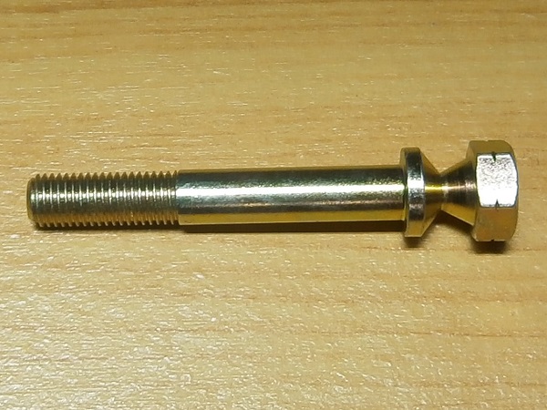
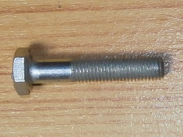
The steering column fixing bolt (51K4006) is a shear bolt. As a safety measure, the head detaches from the body of the bolt when it is screwed in. It is therefore essential to provide a new bolt when dismantling the column.

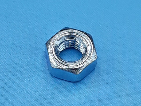
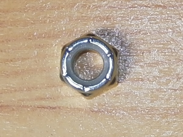
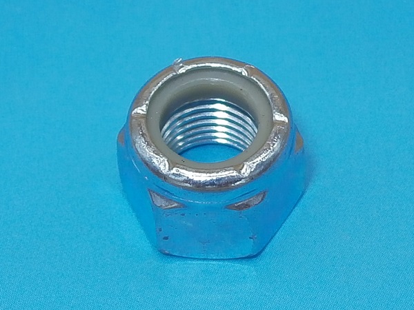
The U-bolt fixing nuts (GFK3322) and shock absorber fixing nuts (GFK3323) are nyloc nuts. Before refitting such a nut, check that the nylon ring is in good condition and ensures locking. If in doubt, for safety, fit a new nut.
When you unscrew a track rod end from the steering rack, be sure to count the number of turns. This will allow you to reinstall the track rod end more accurately. Nevertheless, this will not exempt you from having the alignment adjusted afterwards.
Required Tools
Sponsored links by

Spare Parts
Our Partners


Packaging :
•
All the above parts are sold individually.
Advertisement
Remove the steering column
Op 01
Lift the front of the Mini and secure it on rigid chocks (or axle stands). Use a jack.
Fit the rigid chocks under the body and not under the front subframe because the back of the subframe will be lowered in order to remove the steering rack.
The sheets metal of the Mini's body are very thin and very fragile. Place the body on chocks wide enough to avoid deforming the sheets.
Op 02
Remove the 2 front wheels. Use the 11/16'' socket.
Op 03
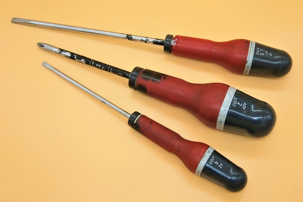
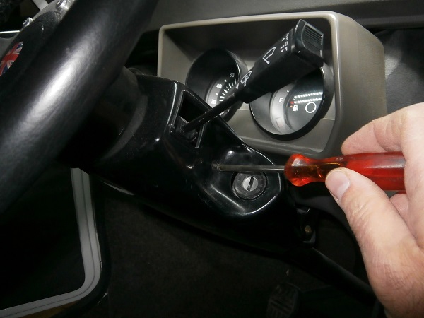
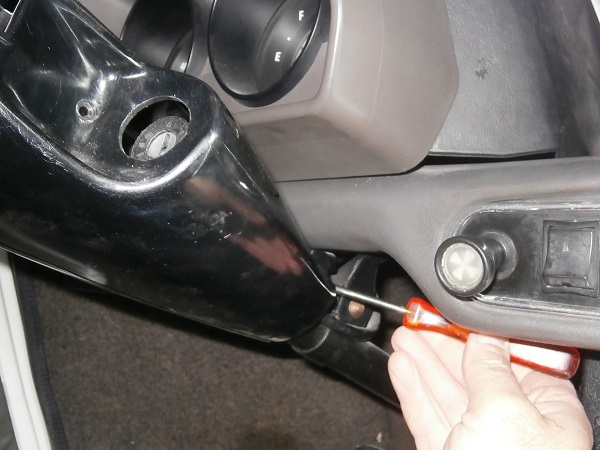
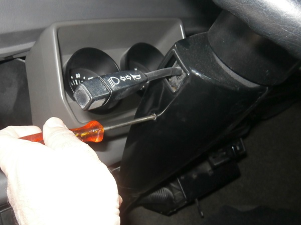
Remove the steering column cowlings. There are 3 fixing screws. Use the Phillips screwdriver.
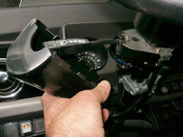
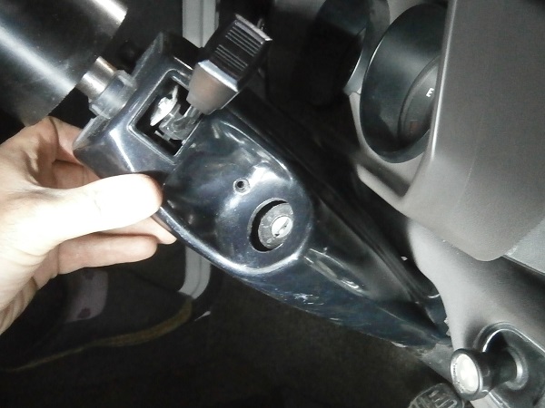
Op 04
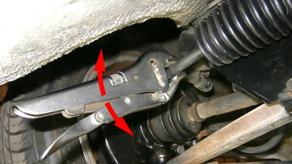
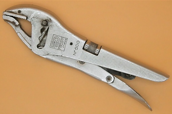
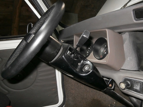
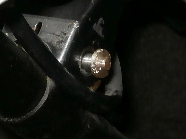
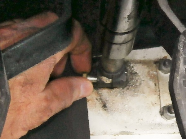
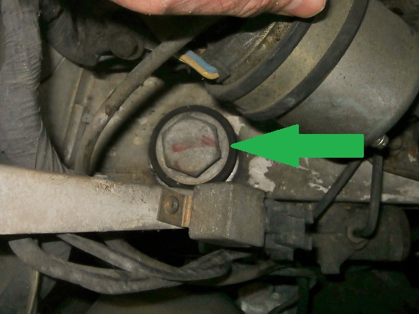
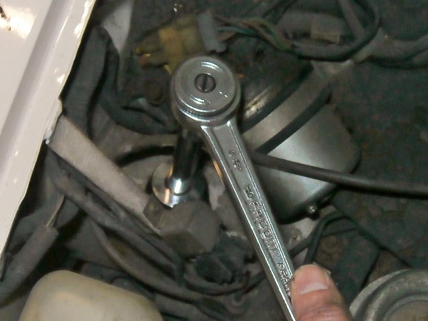
Loosen the column fixing bolt. Use the locking pliers.
Here is the famous column fixing shear bolt. It must be unscrewed even though its head has disappeared. It won't be easy !
If the locking pliers slip on the bolt head, machine two flats. Use a file. The jaws of the pliers will then have a much better grip.
Op 05
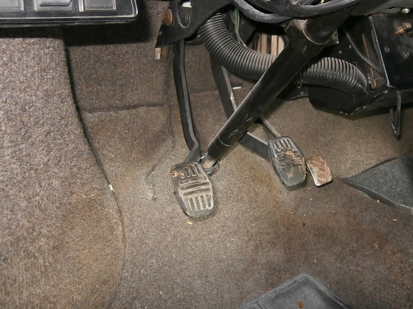
Move the carpet under the driver's feet.
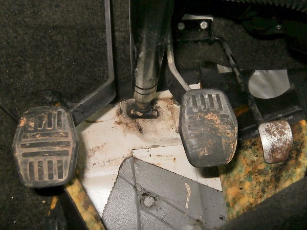
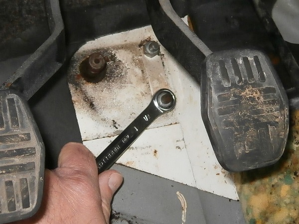
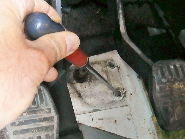
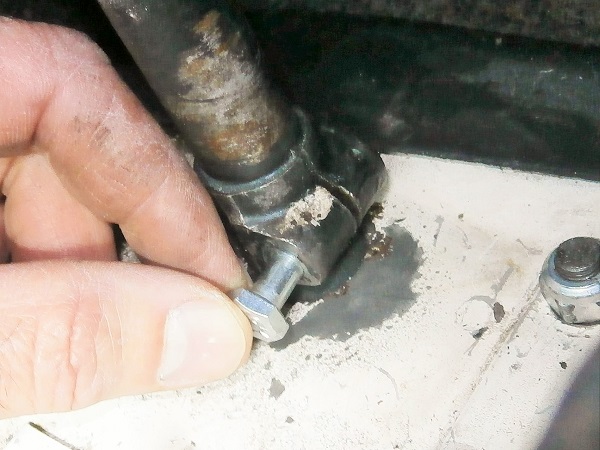
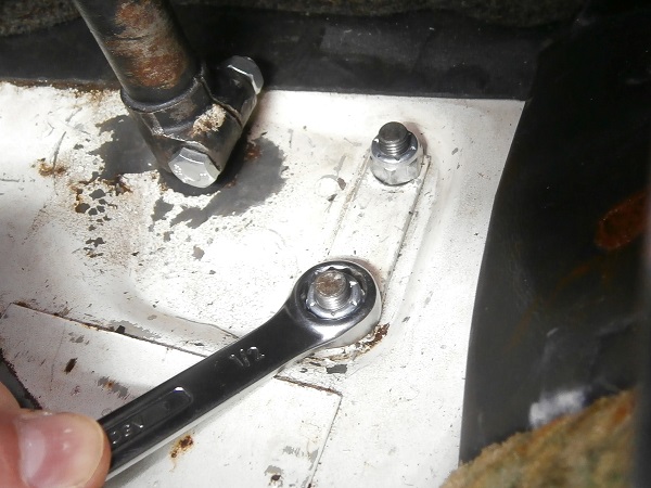
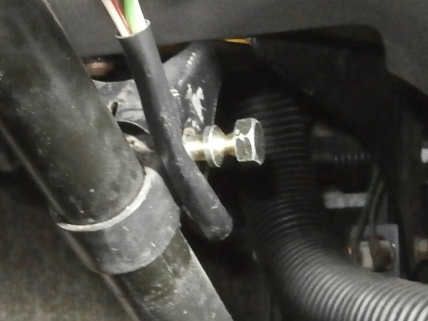
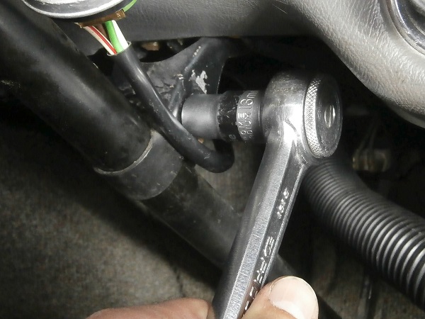
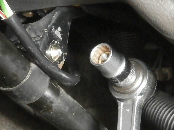
Op 06
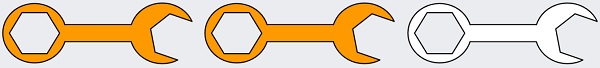
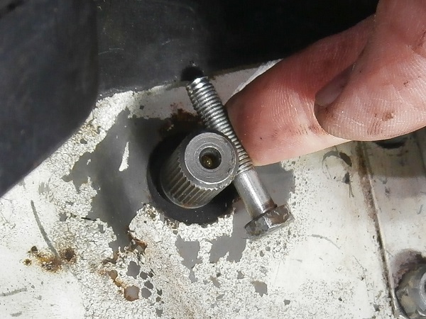
Remove the steering column fixing bolt on the steering rack. Use the 11 mm spanner.
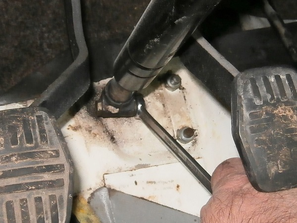
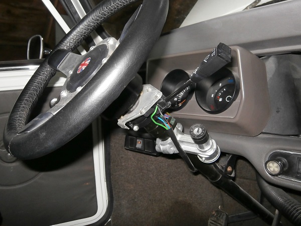
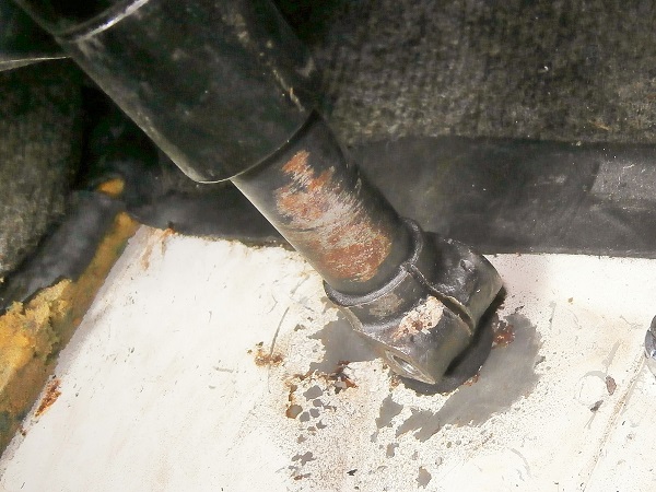
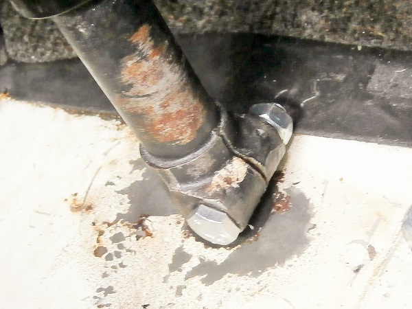
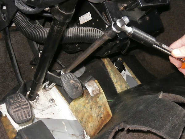
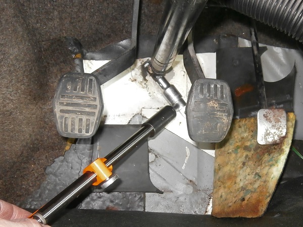
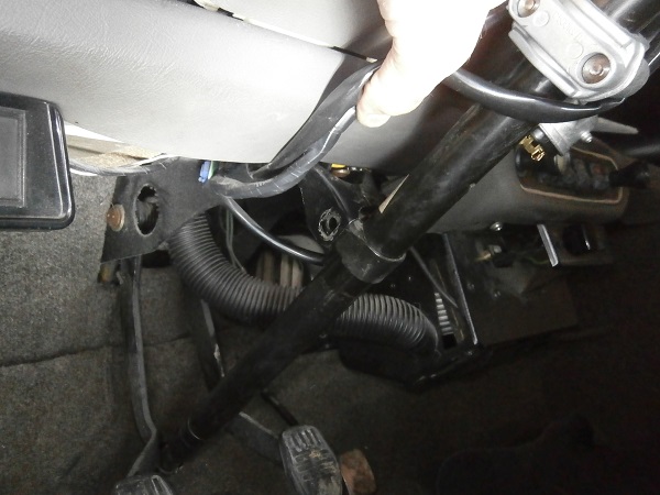
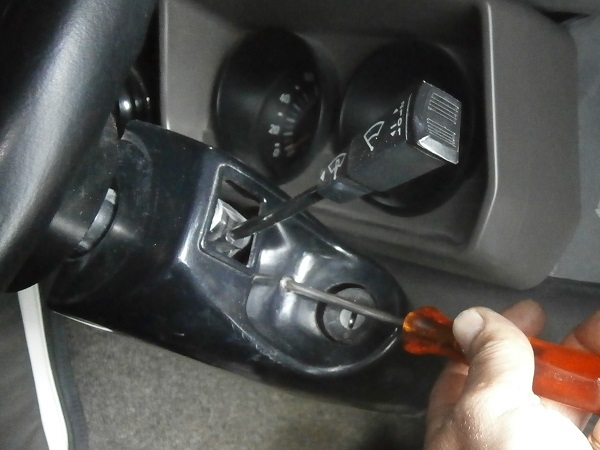
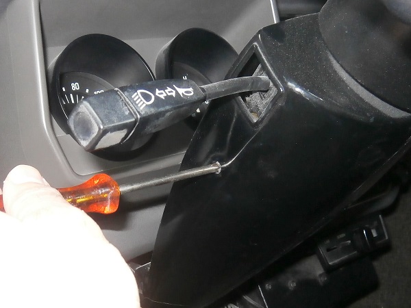
Op 07
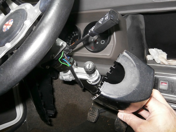
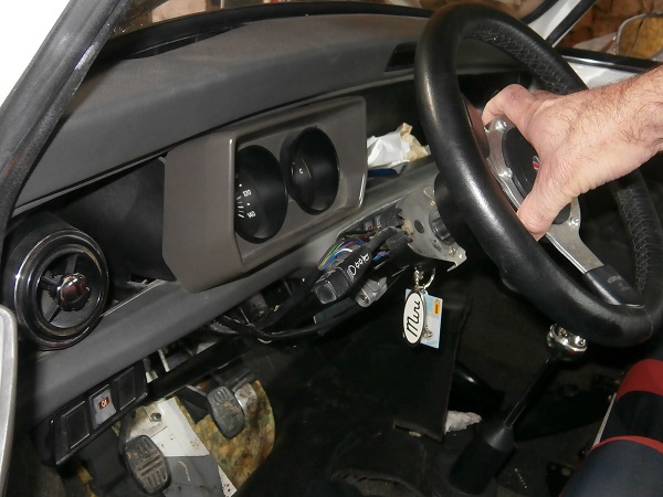
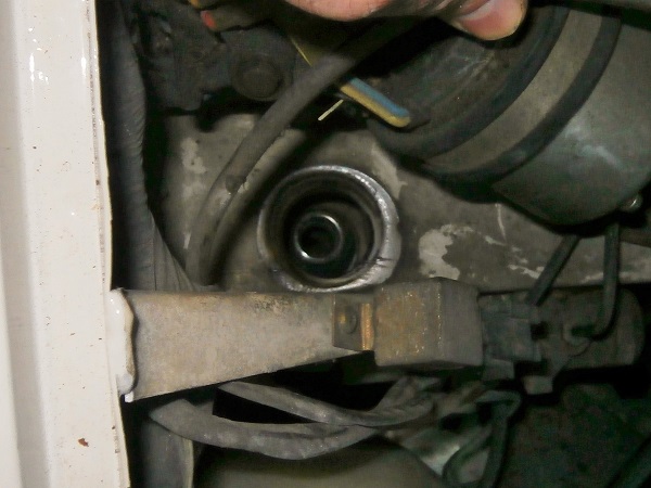
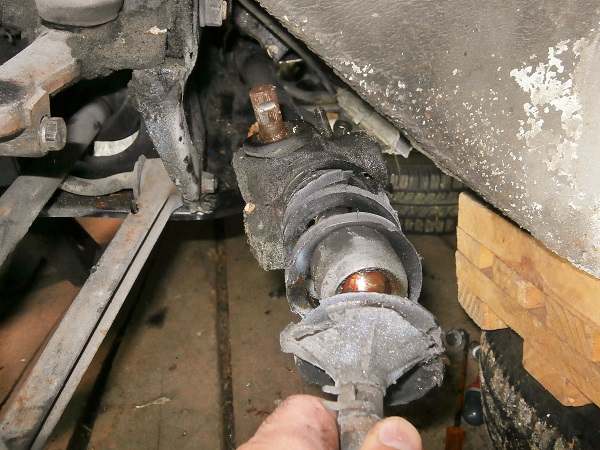
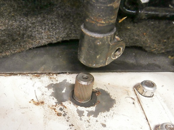
Separate the steering column from the steering rack. Pull firmly on the steering wheel upwards.
If the column does not come off, slightly spread the splines at the bottom of the column (2nd photo). Use the large flathead screwdriver.
Lower the back of the front subframe
Op 08
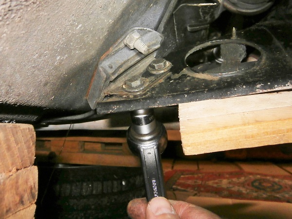
Detach the track rod ends from the steering rack (➔ see the tutorial ''Track rod end change'' Op 03 to 04).
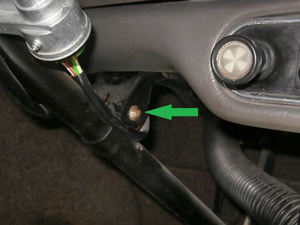
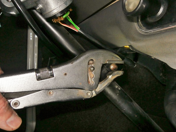
Op 09
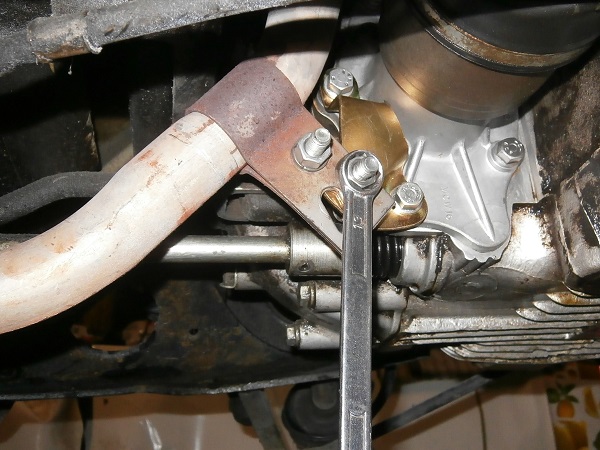
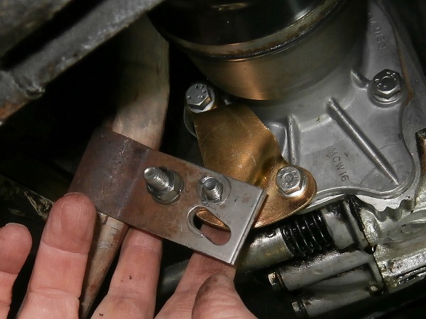
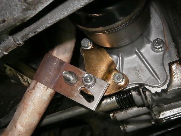
Remove the exhaust downpipe fixing bolt on the engine. Use the 13 mm spanner.
This fixing is located under the engine near the RH driveshaft output.
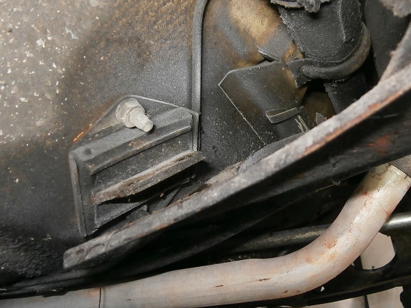
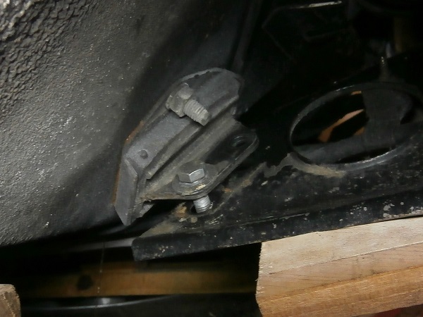
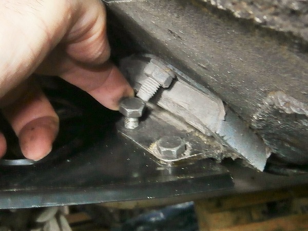
Op 10
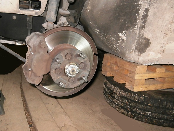
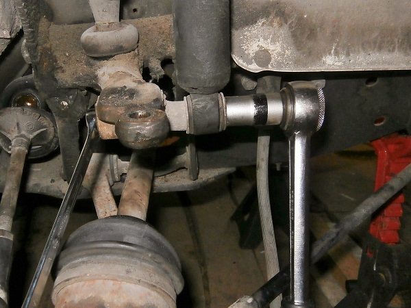
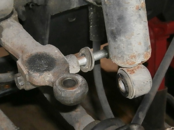
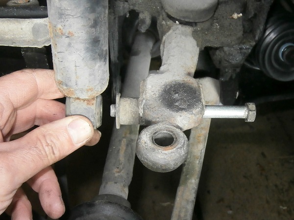
Separate the shock absorbers from the upper suspension arms. Use the 14 mm socket.
Note the stacking of the spacer and washers to facilitate reassembly.
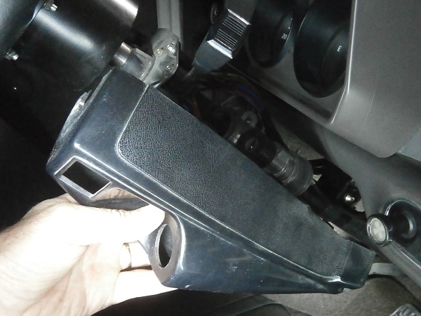
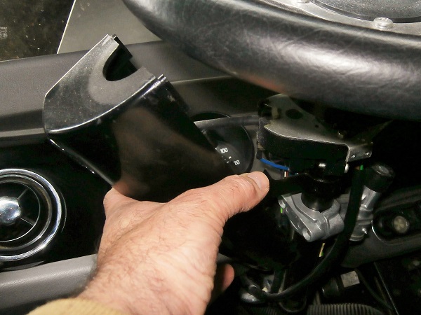
Op 11
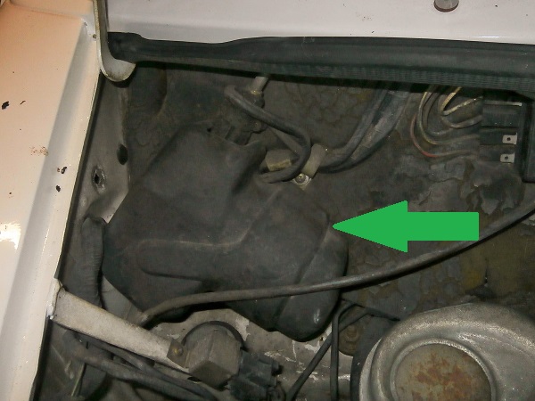
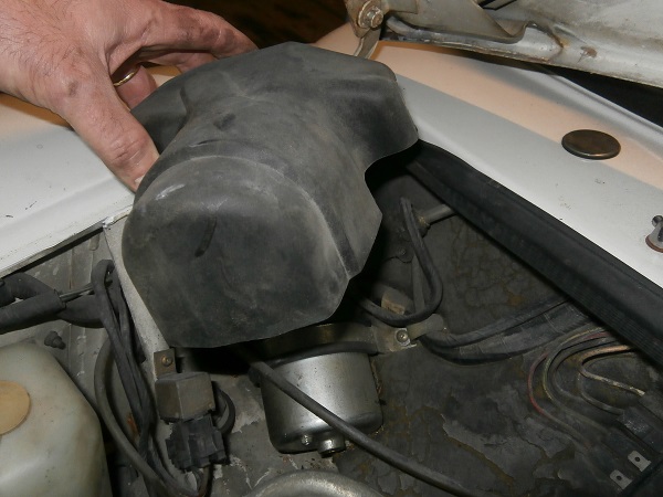
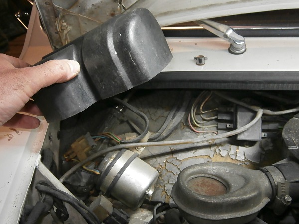
Remove the plastic cover of the wiper motor.
This part is simply clipped on. Simply tear it off by hand.
This operation is necessary to be able to access the bolt located underneath.
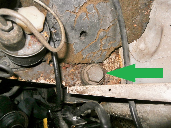
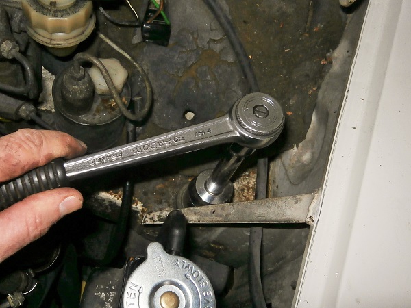
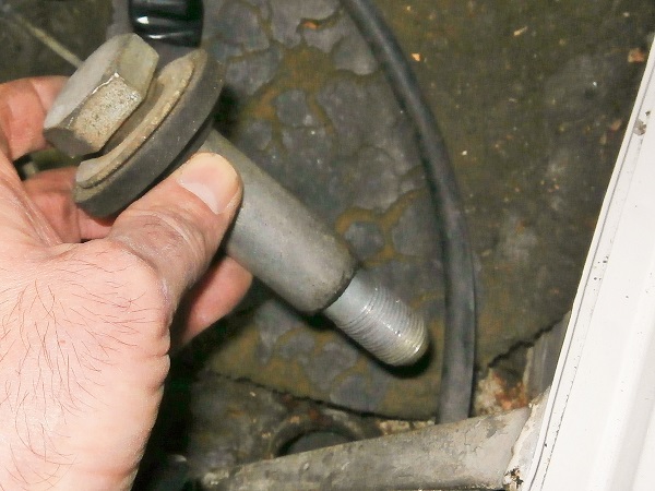
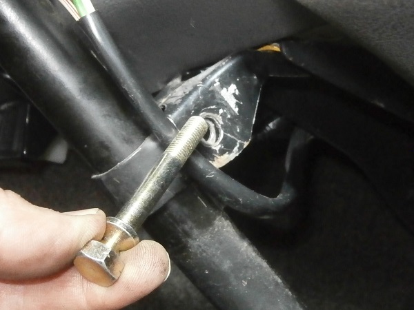
Op 12
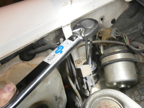
Remove the 2 upper fixing bolts (LH and RH) of the front subframe. Use the 34 mm socket.
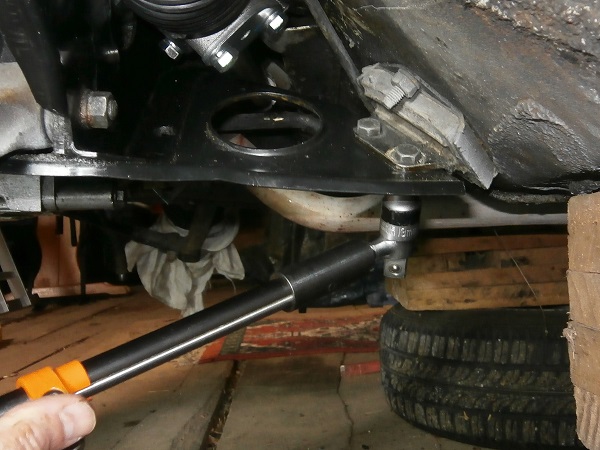
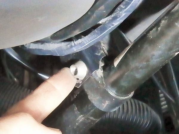
Op 13
Remove the rear fixing bolts of the front subframe on the LH and RH sides. Use the 13 mm spanner.
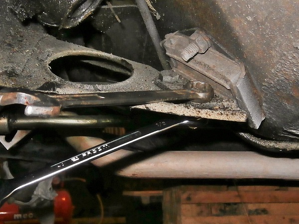
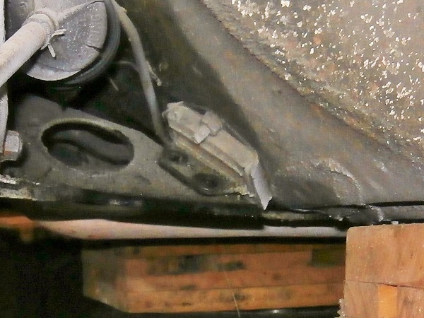
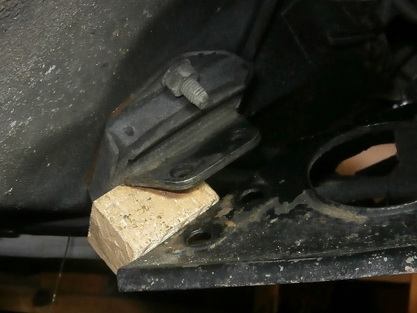
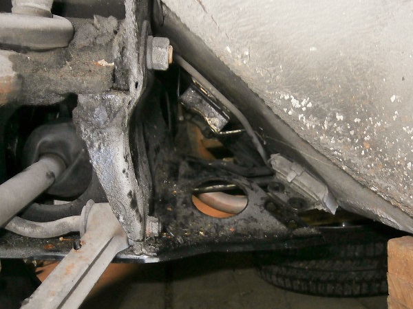
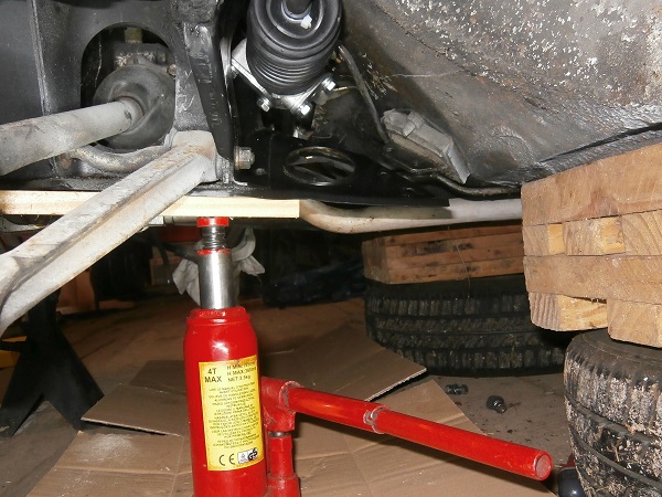
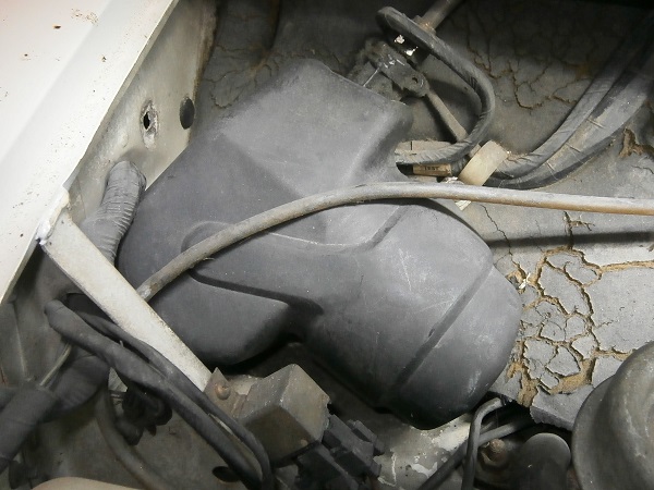
Op 14
Lower the back of the subframe. Use wooden chocks if necessary (2nd photo).
Remove the steering rack
Op 15
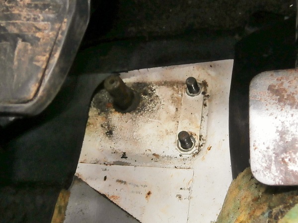
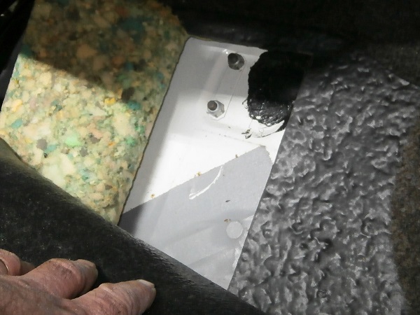
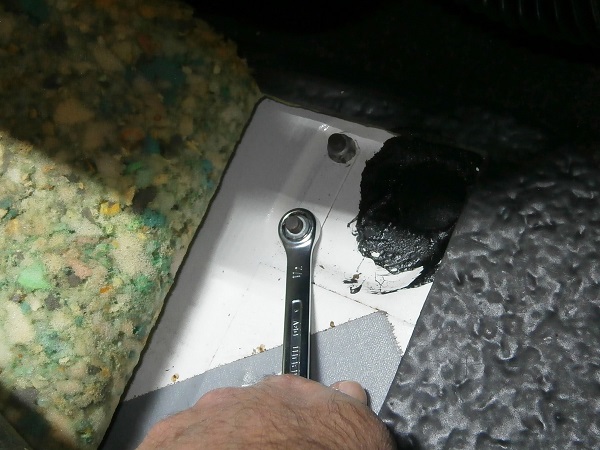
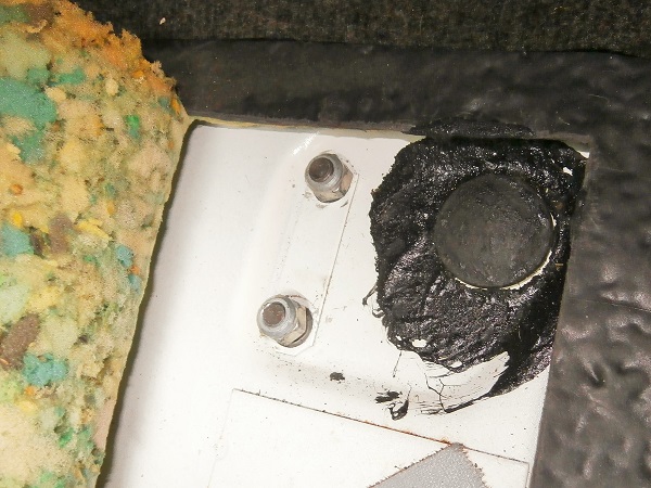
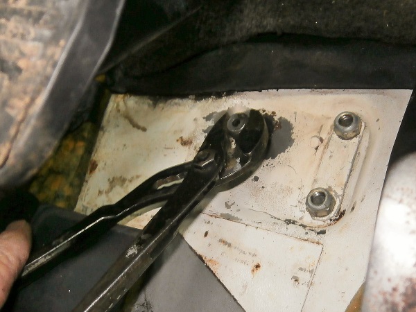
Unscrew the 4 nuts of the steering rack fixing U-bolts. Use the 13 mm spanner.
There is a U-bolt under the driver's feet and a U-bolt under the front passenger's feet. The nuts are under the carpet.
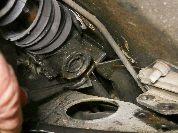
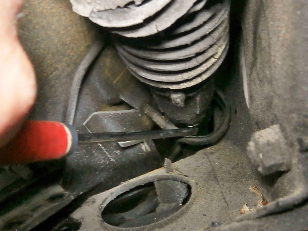
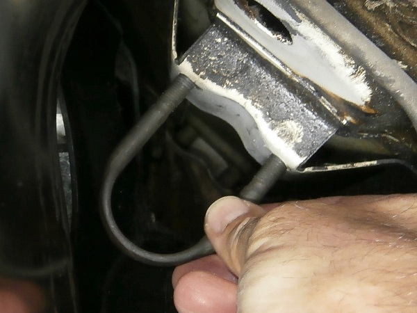
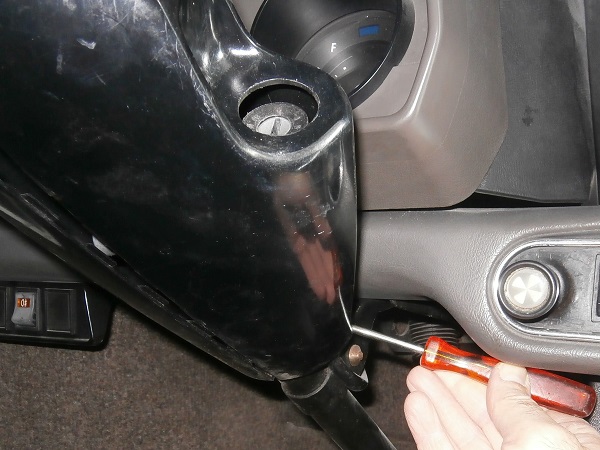
Op 16
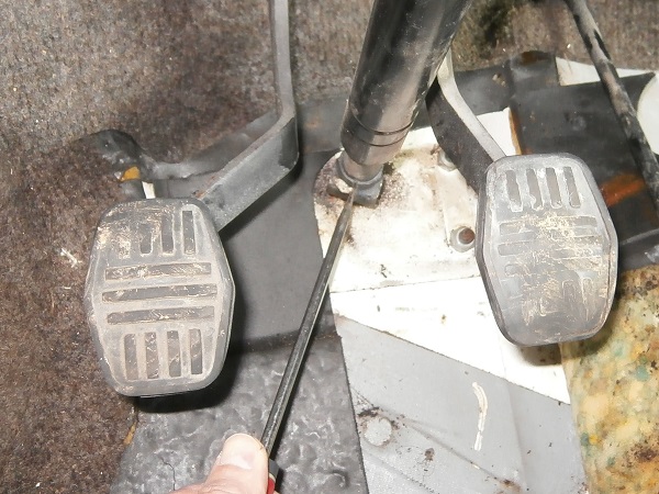
Push back the steering rack fixing U-bolts. Use the screwdriver.
Op 17
Remove the steering rack fixing U-bolts. Use the screwdriver or a crowbar.
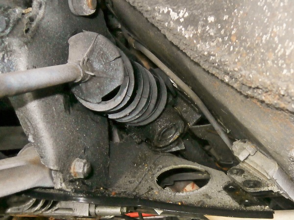
Op 18
Remove the steering rack (from the driver's side).
It's really not easy. The subframe must be lowered sufficiently.
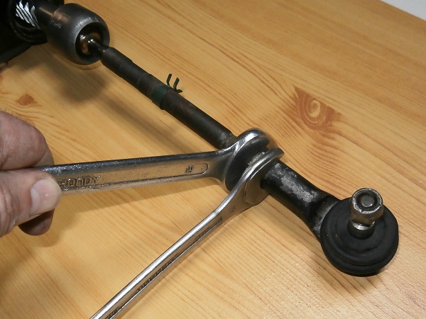
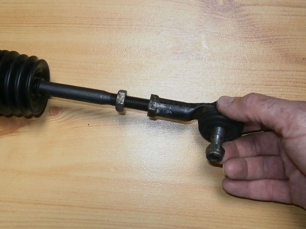
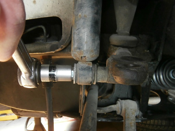
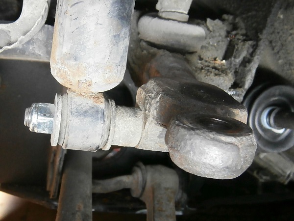
Op 19
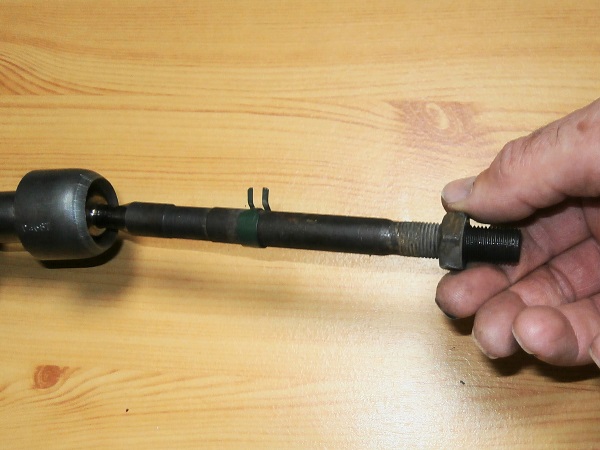
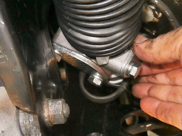
Remove the track rod end and its half lock nut. Use the two 19 mm spanners.
Count the number of turns when unscrewing the track rod end. This will allow it to be positioned approximately during reassembly.
Advertisement
Fit the steering rack
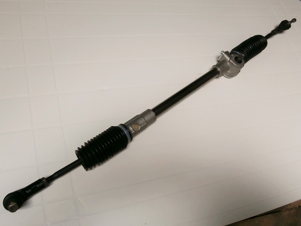
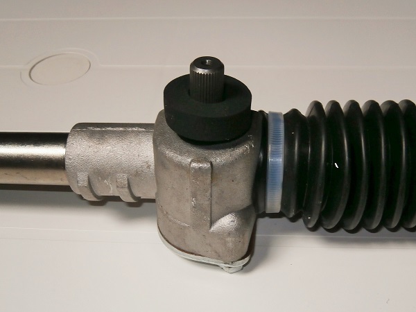
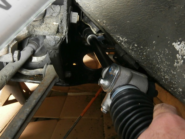
Op 20
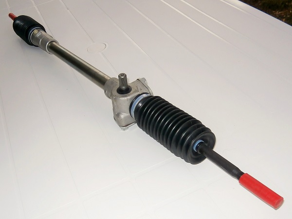
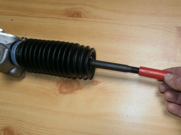
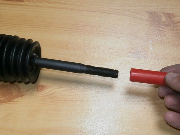
Remove the thread protection from the new steering rack (FAM7307). Pull firmly by hand.
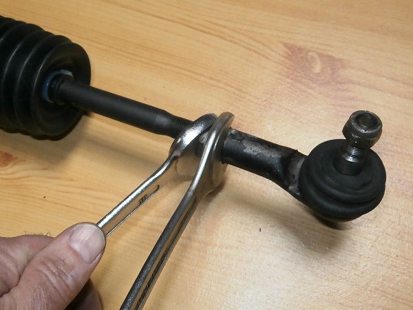
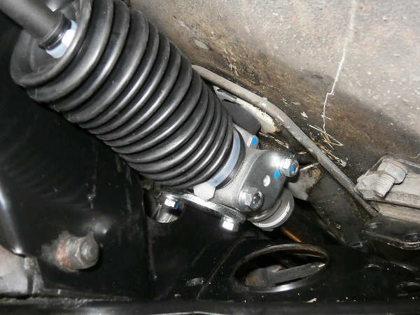
Op 21
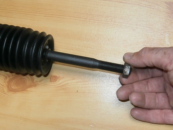
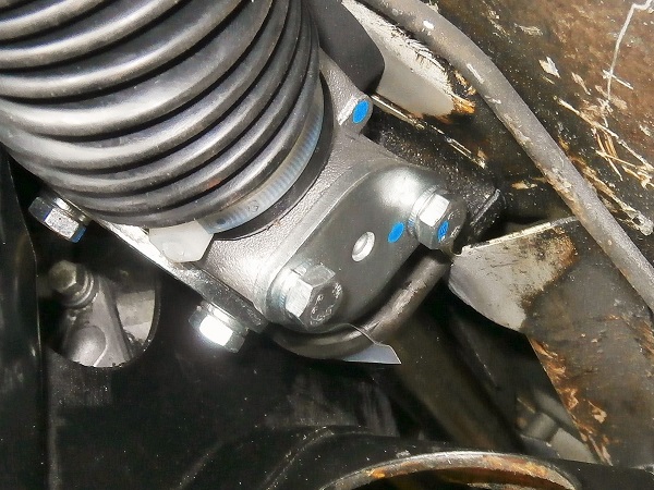
Fit the half lock nut and the track rod end on the new steering rack.
Tighten the half lock nut firmly against the track rod end. Use the two 19 mm spanners.
Screw the track rod end in the same number of turns as during disassembly. This allows a first approach to the front wheels alignment.
The tightening torque of the track rod end half lock nut is 52 mN. Unfortunately, it is impossible to use a torque wrench in this location. Tighten very hard !
Op 22
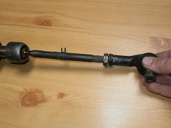
Proceed in the same way with the second track rod end.
The track rods must be of the same length. Check that the thread lengths protruding from the track rod ends are the same.
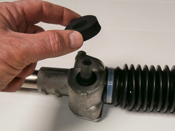
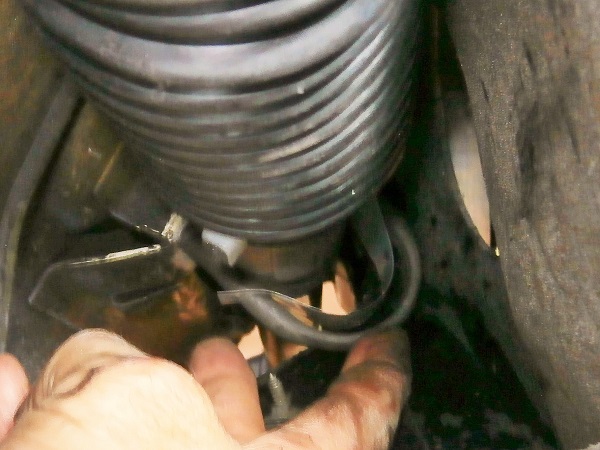
Op 23
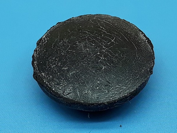
Fit the foam seal (21A30) on the rack.
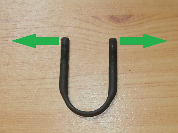
Op 24
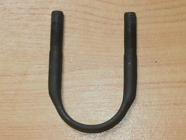
Check that the steering rack fixing U-bolts (2A6208) fit easily into the holes in the floor.
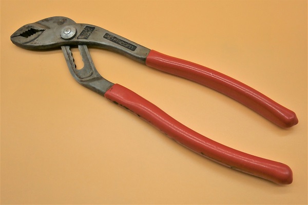
If necessary, widen or tighten the spacing of the U-bolts. Use the multigrip pliers (the U-bolts are very flexible). This will greatly facilitate the reassembly operations.
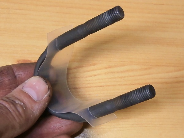
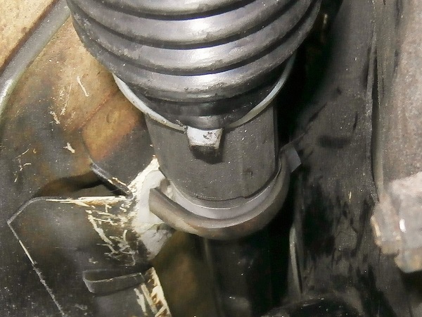
Op 25
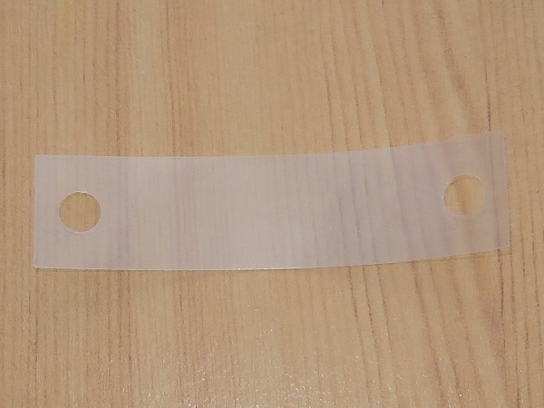
Fit the anti-friction strip (21A2553) on each of the two U-bolts.
Op 26
Fit the rack.
Op 27
Fit the U-bolt on the passenger side. The hands of a midwife are essential.
Lightly screw in the 2 nuts (GFK3322) so that the U-bolt remains in place.
Op 28
Fit the U-bolt on the driver's side.
Lightly screw in the 2 nuts so that the U-bolt remains in place.
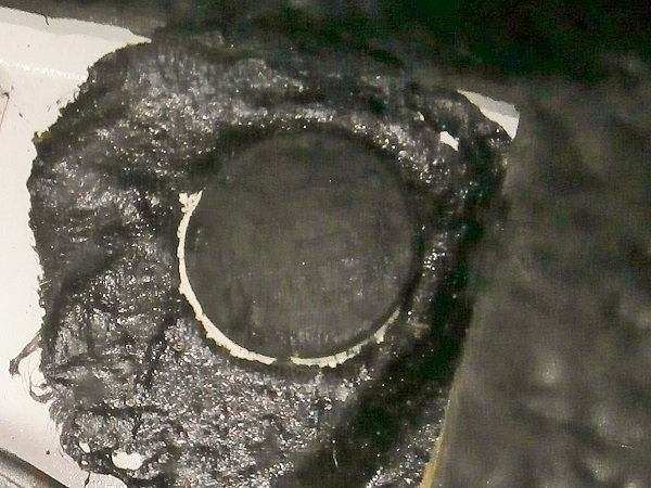
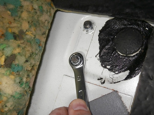
Op 29
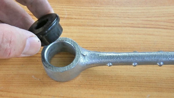
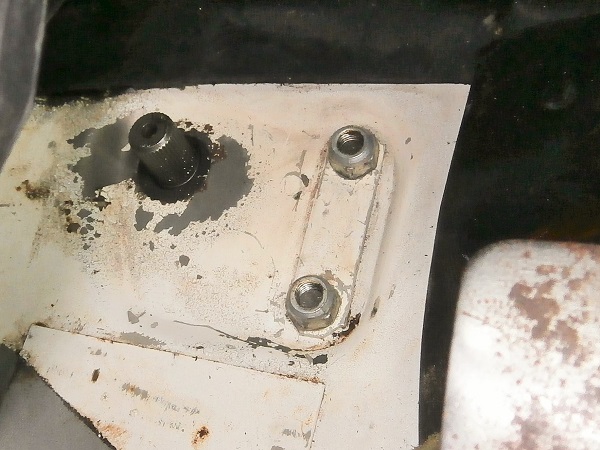
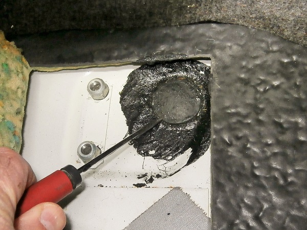
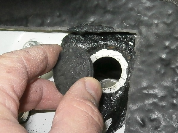
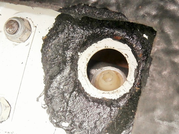
Remove the floor rubber plug. Use a flathead screwdriver.
This orifice gives access to the steering rack.
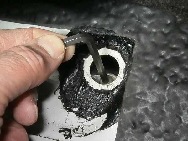
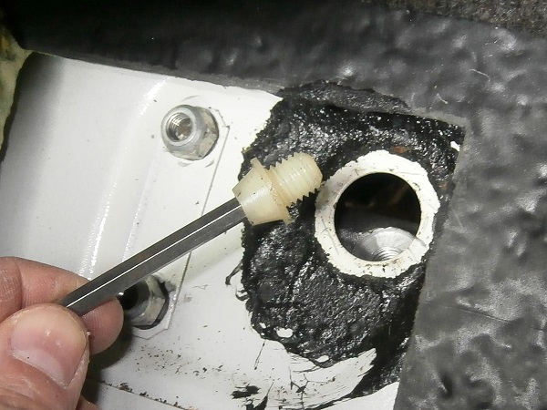
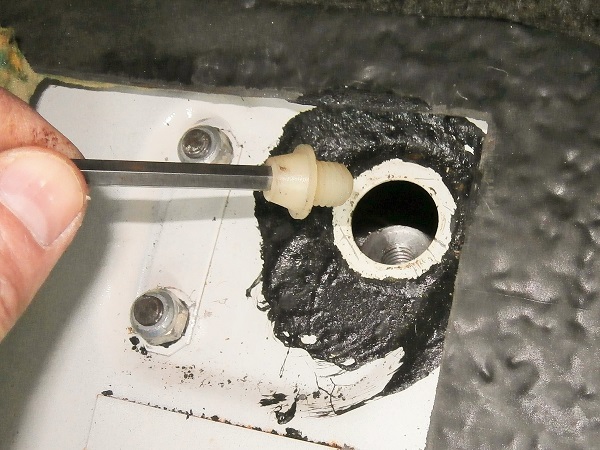
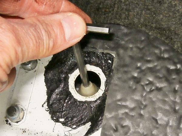
Op 30
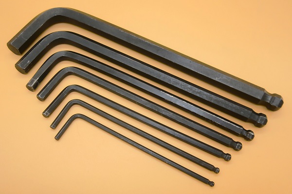
Remove the steering rack centering plug. Use a 5 mm allen key.
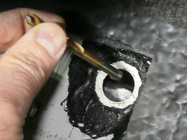
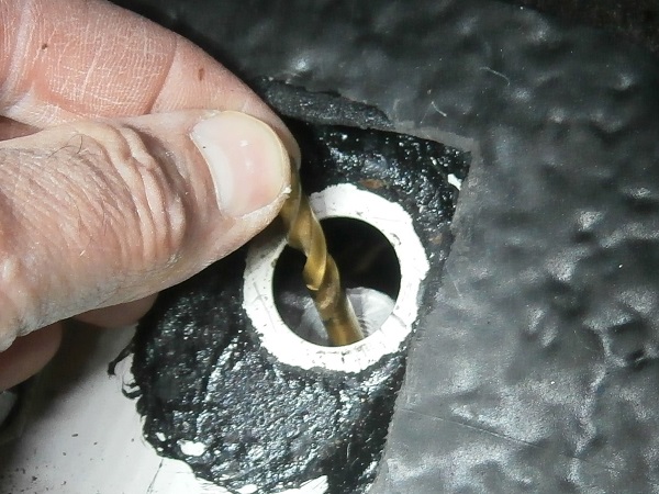
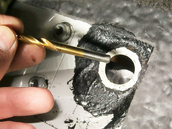
Op 31
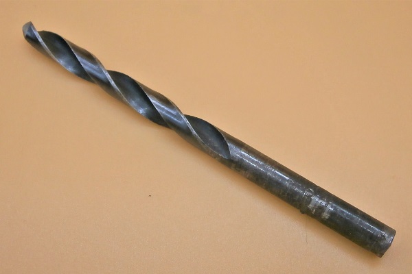
Engage a rod with a diameter of 6 mm in the rack tube and the rack orifice. Use the body of a 6 mm drill bit.
If the rack is not correctly positioned, operate the steering (2nd photo). Use the multigrip pliers.
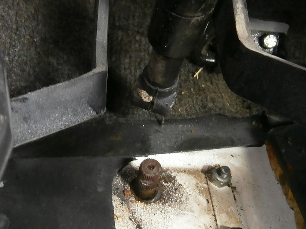
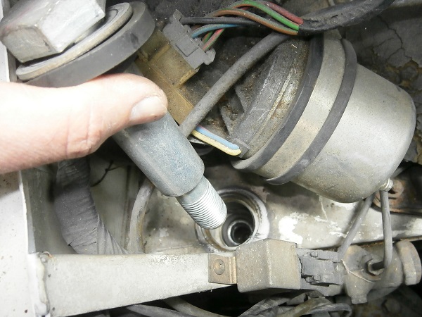
Op 32
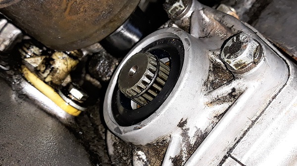
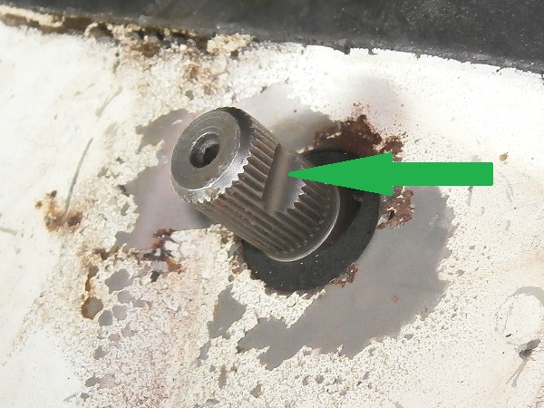
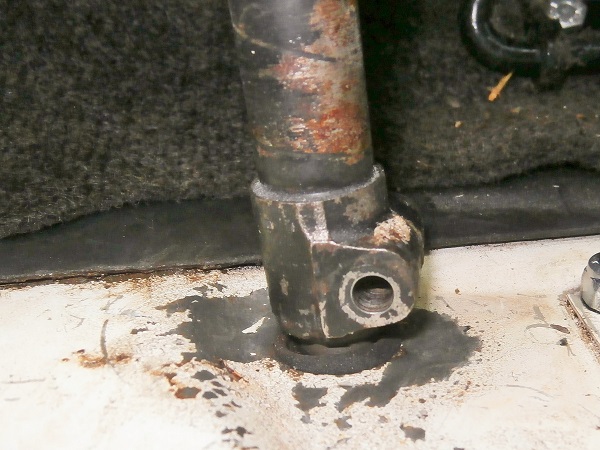
Identify the position of the notch on the splined steering rack shaft.
This is where the column fixing screw on the rack should go.
Op 33
Engage the steering column on the splined shaft.
Ensure the angular position of the column in relation to the splined shaft is correct so that the bolt can be engaged in the next operation.
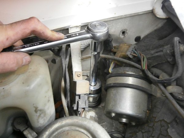
Op 34
Fit the column fixing bolt (BH604111), its washer (GFK1124) and its nut (GFK3211). Use the 11 mm spanner.
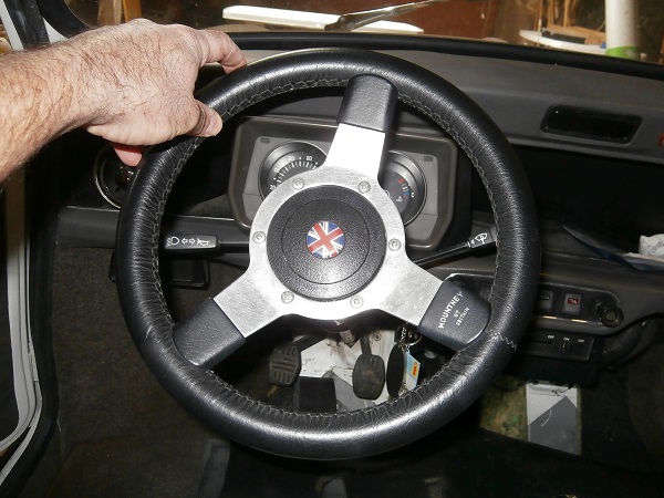
The steering rack is centered (immobilized by the drill bit) and the steering column is fixed on the rack. The steering wheel should therefore be perfectly centered. If this is not the case, plan to remove the steering wheel to correct its position.
Op 35
Remove the drill bit.
Screw on the steering rack plug. Use the 5 mm allen key.
Fit the floor rubber plug (14A7091) on the floor.
Op 36
Turn the steering wheel from one stop to the other.
Check that the steering wheel turns freely without any hard spots.
Op 37
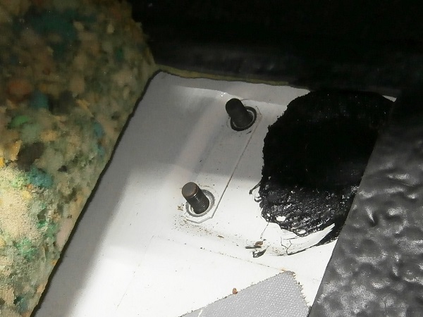
Gradually tighten the 4 nuts of the rack U-bolts. Use the 13 mm spanner.
Check that the length of thread protruding from each of the 4 nuts is identical.
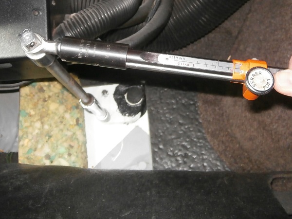
Op 38
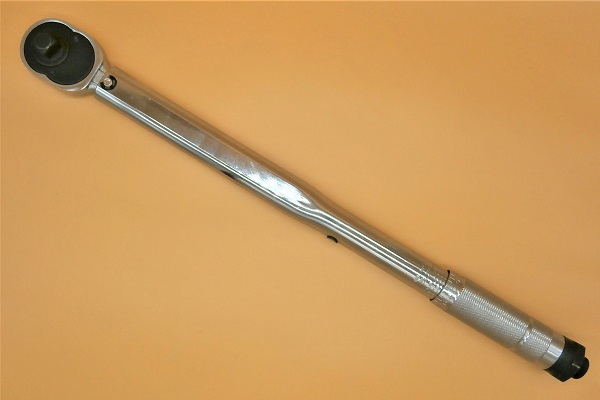
Tighten the 4 nuts of the rack U-bolts to a torque of 15 mN.
Use the torque wrench + the 13 mm socket.
Op 39
Tighten the column fixing bolt nut to a torque of 16 mN. Use the torque wrench + the 11 mm socket.
Fit the back of the front subframe
Op 40
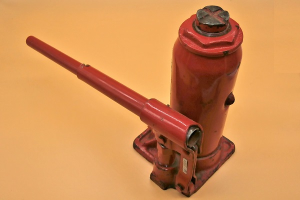
Put the rear part of the subframe back in place. Use a bottle jack to lift the subframe.
Fit a fixing bolt when raising the subframe. This helps to guide it.
Op 41
Fit the 4 rear fixing bolts of the front subframe. Use the 13 mm socket.
Tighten the 4 bolts to a torque of 30 mN. Use the torque wrench.
Op 42
Fit the 2 upper fixing bolts (LH and RH) of the front subframe. Use the 34 mm socket.
Tighten the 2 bolts to a torque of 67 mN. Use the torque wrench.
Op 43
Fit the plastic cover on the wiper motor.
Op 44
Secure the shock absorbers to the suspension arms. Use the 14 mm socket.
Ensure that the mounting order of the spacer, washers and nut (GFK3323) is correct.
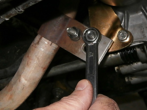
Op 45
Fit the exhaust downpipe fixing bolt on the engine. Use the 13 mm spanner.
Op 46
Fit the track rod ends on the steering rack (➔ see the tutorial ''Track rod end change'' Op 11 to 12).
Advertisement
Fit the steering column
Op 47
Fit the nut (21H295) and the bolt (51K4006) for steering column fixing.
Screw in until the head of the bolt breaks off.
Make sure to raise the steering column sleeve before tightening the bolt. If the sleeve is too low, in the next operation, the 2 plastic cowlings will bump against the column collar (in the lower part) and it will not be possible to position them correctly.
Try positioning the 2 cowlings before breaking the head of the bolt.
Op 48
Fit the 2 steering column cowlings.
Screw in the 3 fixing screws. Use a Phillips screwdriver.
Op 49
Refit the wheels and screw on the nuts. Use the 11/16'' socket.
Lower the Mini to the ground. Remove the chocks or axle stands.
Tighten the nuts to the torque corresponding to the type of rim. Use the torque wrench.
The tightening torque of the wheel nuts is :
• 63 mN for steel rims.
• 50 mN for alloy rims.
• 63 mN for steel rims.
• 50 mN for alloy rims.
Op 50
Have the front wheel alignment adjusted by a specialist.
The End