
This tutorial is also available in French
➔

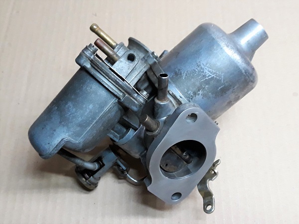
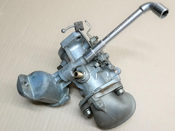
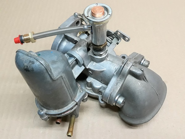
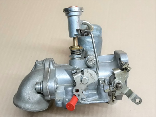
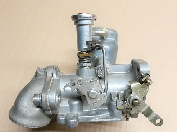
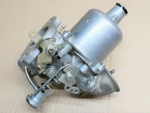
HS4 waxstat carburetor maintenance on Austin Mini
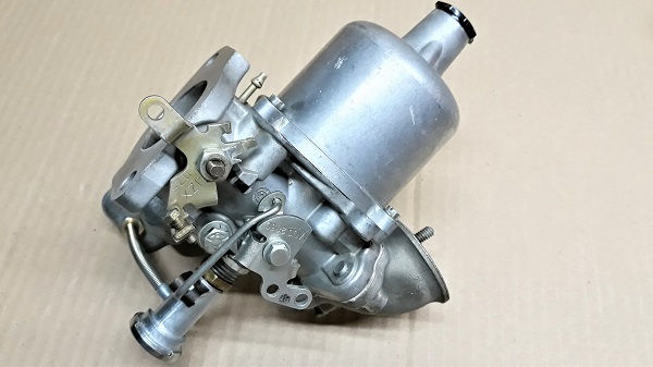
Vehicle ➔ Mini 1000 year 1991 automatic gearbox
Difficulty ➔ Easy

Time ➔ 3 hours
Summary
Advertisement
Advertisement

Recommendations

The HS4 carburetor service kit (CSK65 kit) does not include the butterfly and its spindle. Before ordering, check the butterfly spindle on the carburetor. If it has play, order the HS4 carburetor rebuild kit (CRK121 kit).
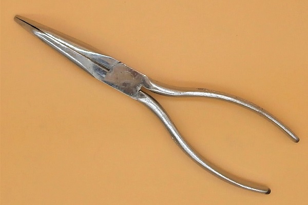
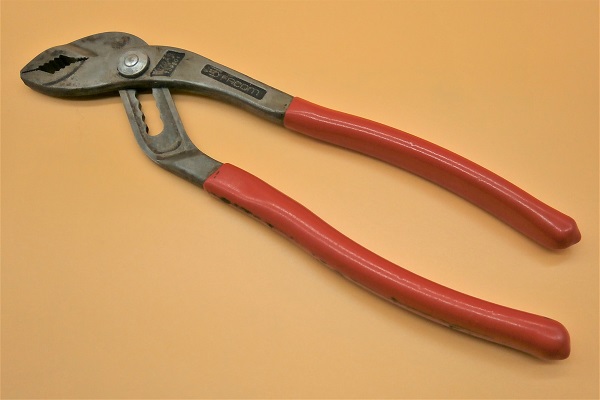
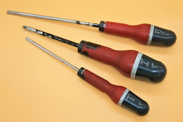
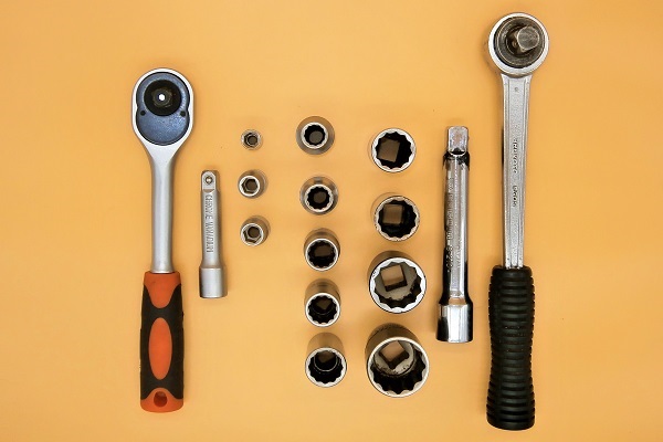
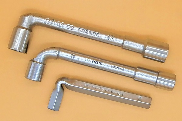
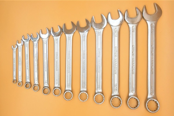
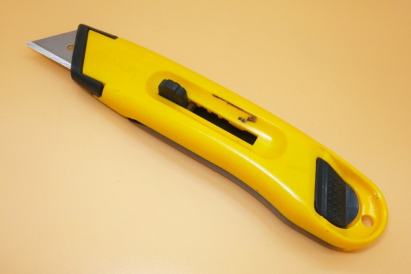
Required Tools
Sponsored links by

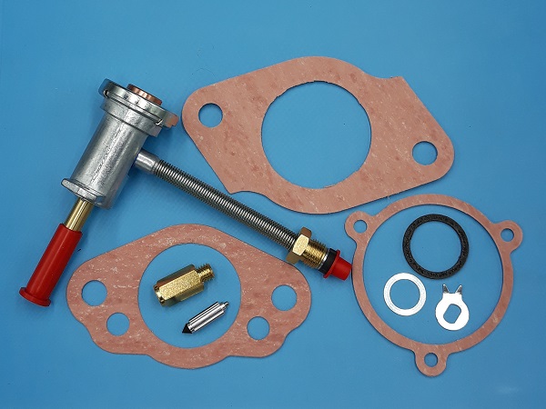
Spare Parts
Our Partners


Packaging :
•
GSK65 : The carburetor service kit includes gaskets, waxstat jet, float needle and accelerator shaft washer.
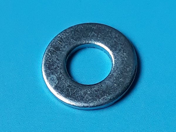
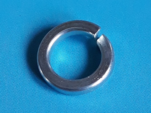
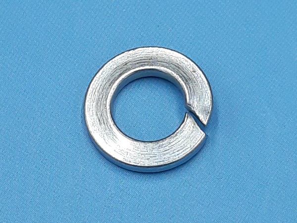
• All the washers above are sold individually.
• All the washers above are sold individually.
Advertisement
Disassemble the carburetor
Op 01
Remove the air filter box (➔ see the tutorial ''HS4 air filter change'' Op 01 to 02).
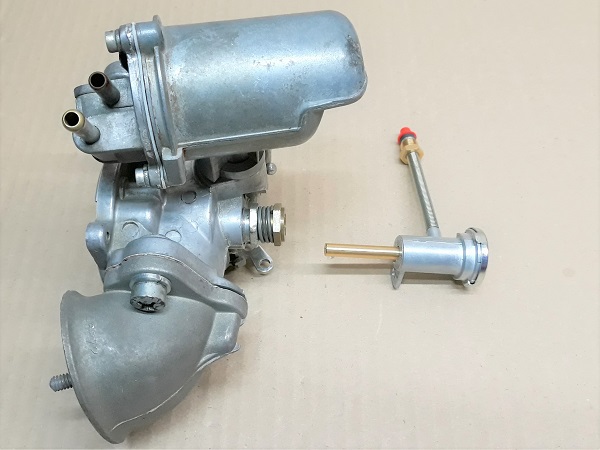
Op 02
Remove the carburetor (➔ see the tutorial ''HS4 carburetor removal'' Op 02 to 12).
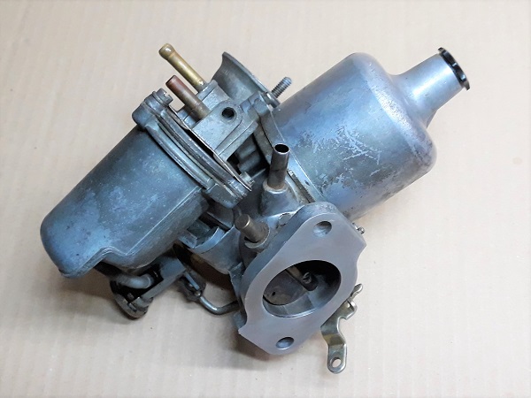
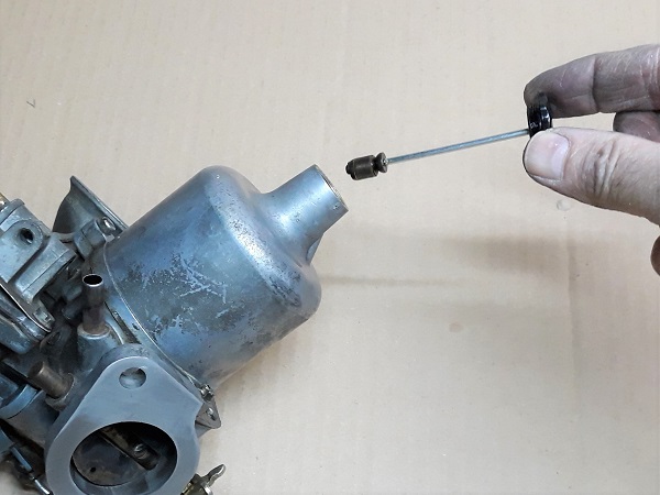
Op 03
Remove the dashpot damper. Unscrew by hand.
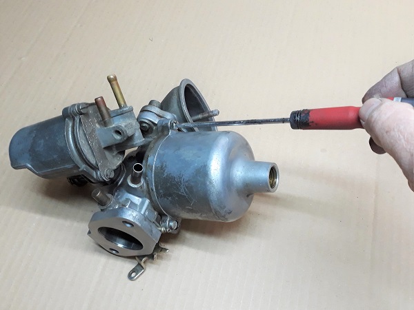
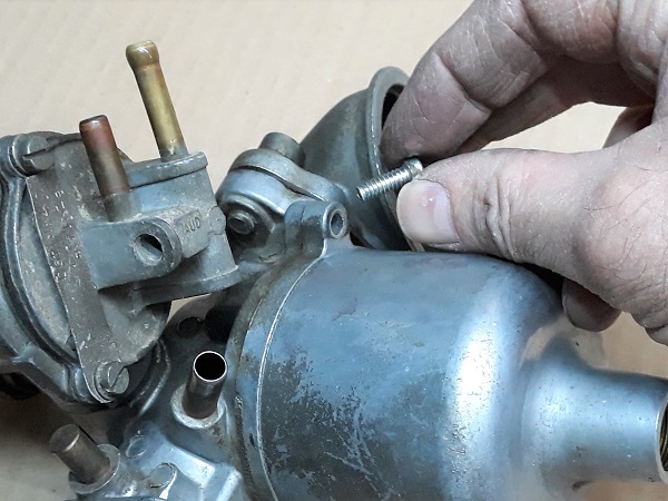
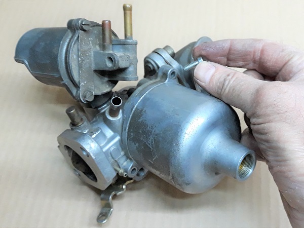
Op 04
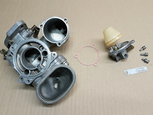
Unscrew the 3 screws of the dashpot cover. Use the flathead screwdriver.
Remove the dashpot cover. Pull by hand.
Remove the dashpot cover straight without tilting it. This could damage the piston or the needle.
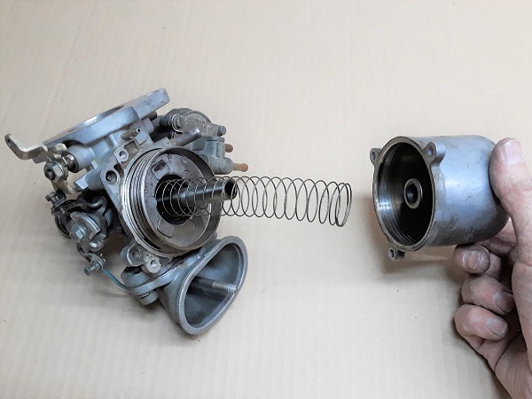
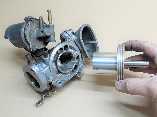
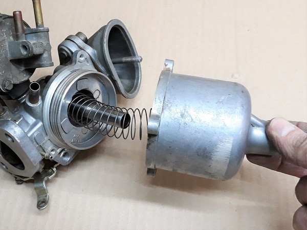
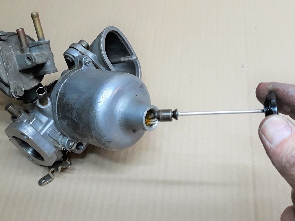
Op 05
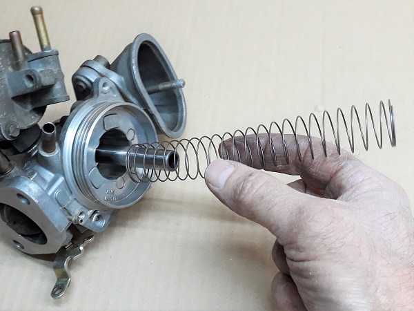
Remove the piston spring.
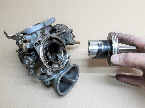
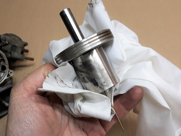
Carefully remove the piston + needle assembly. Pull by hand.
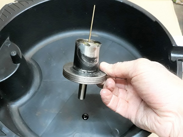
Drain the used oil out of the damper.
Warning! The piston + needle assembly is very fragile.
Op 06
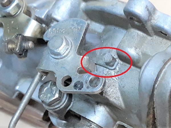
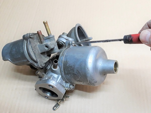
Release the choke lever return spring. Use a screwdriver to disengage it from its support.
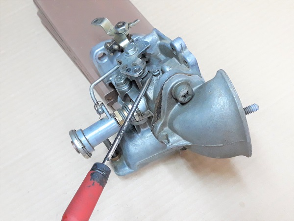
Op 07
Remove the retaining clip of the choke/jet linkage rod. Use a flathead screwdriver.
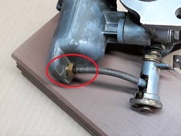
Op 08
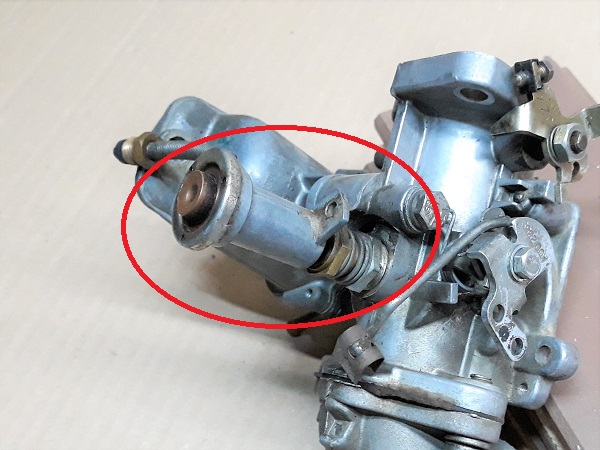
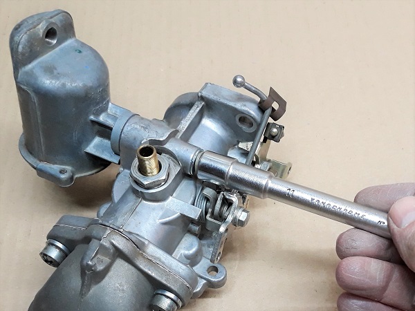
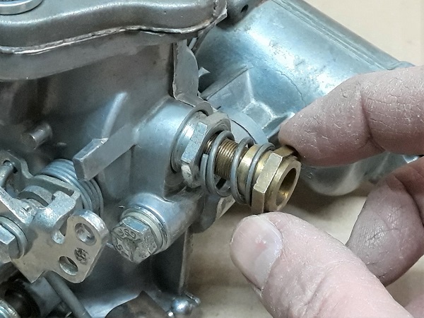
Unscrew the nut securing the jet hose to the float chamber. Use the 7/16'' spanner.
Sometimes, the seal and the small washer remain stuck in the tapping of the float chamber. Do not forget to remove them.
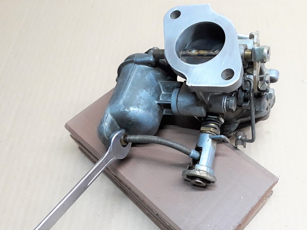
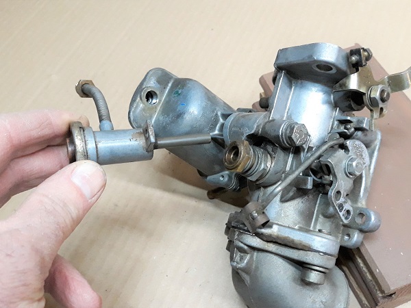
Op 09
Remove the jet from its housing. Pull by hand.
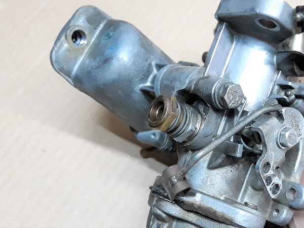
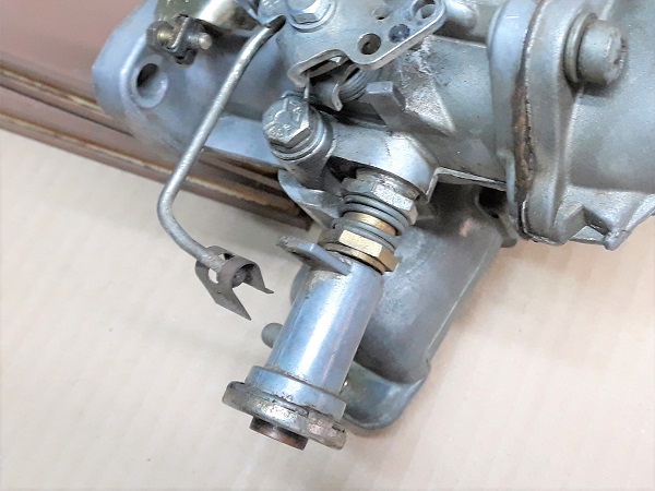
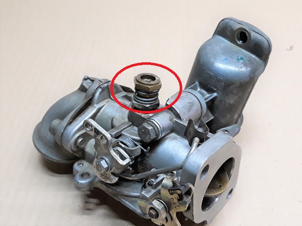
Op 10
Remove the jet adjusting nut and jet locking spring. Unscrew by hand.
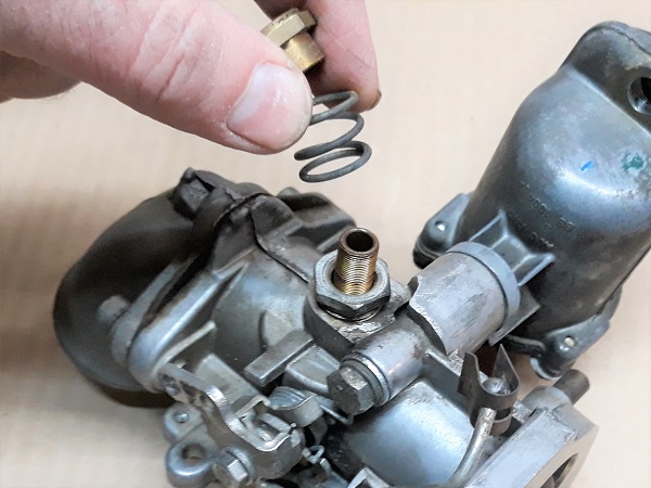
Op 11
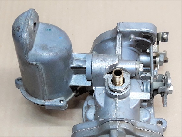
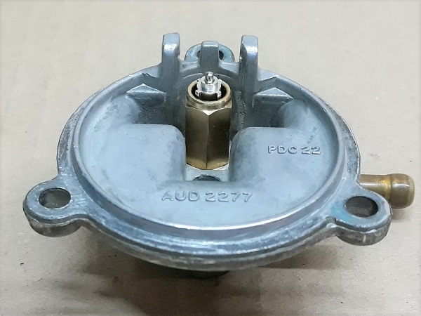
Remove the 3 screws securing the float chamber cover. Use a flathead screwdriver.
Recover the carburetor number plate.
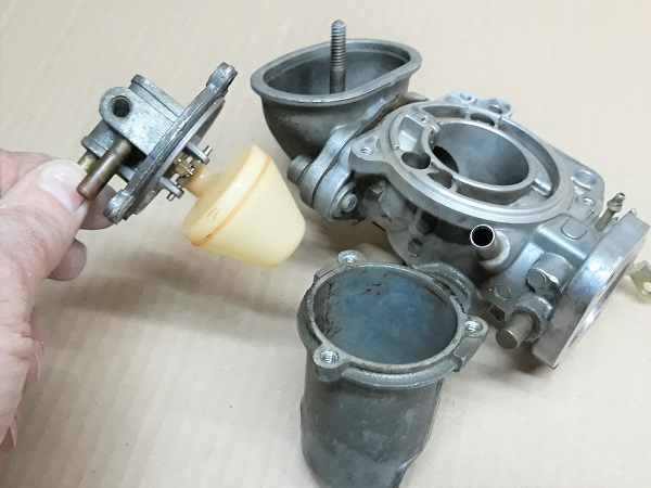
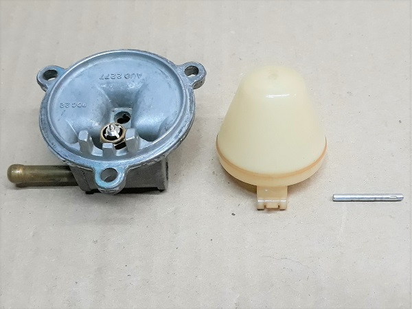
Op 12
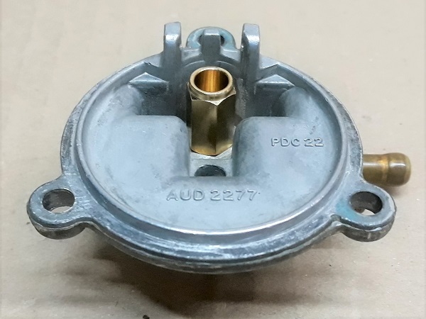
Remove the float chamber cover + float assembly. Pull by hand.
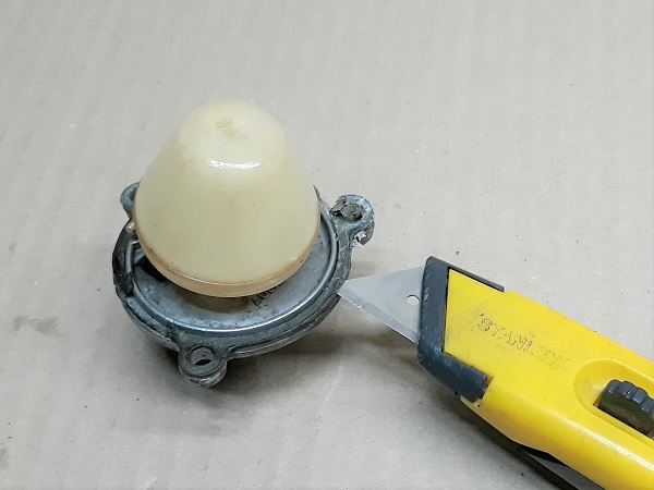
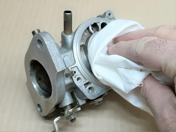
Op 13
Remove the gasket and perfectly clean the support surface of the cover. Use a cutter.
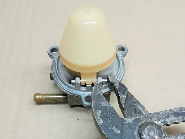
Op 14
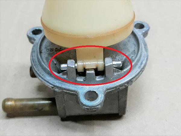
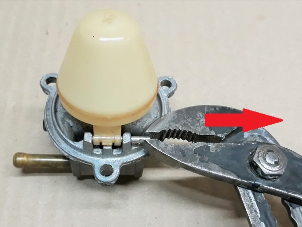
Remove the float lever pin. Use the pliers.
Remove the pin from the knurled side. It will be easier.
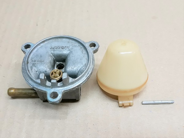
Op 15
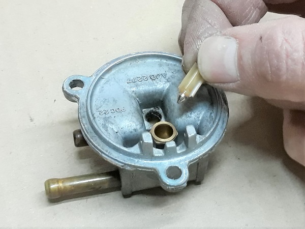
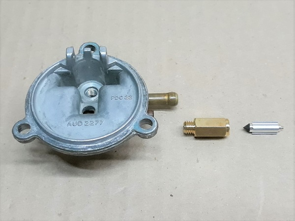
Remove the needle.
Unscrew and remove the needle seat. Use a 9 mm socket.
Op 16
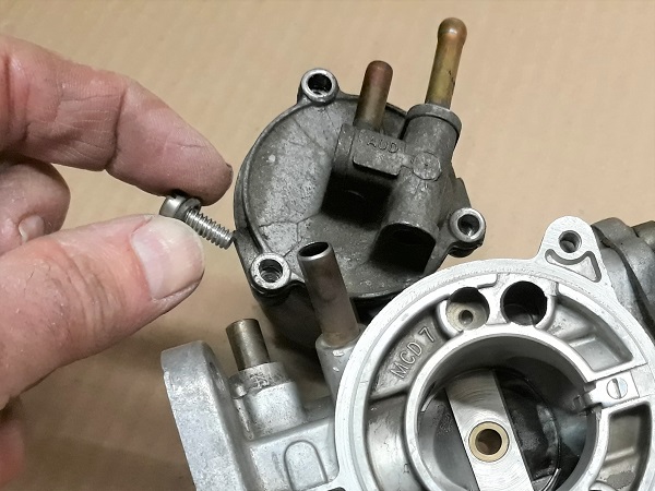
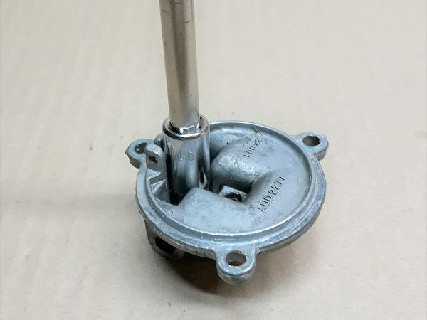
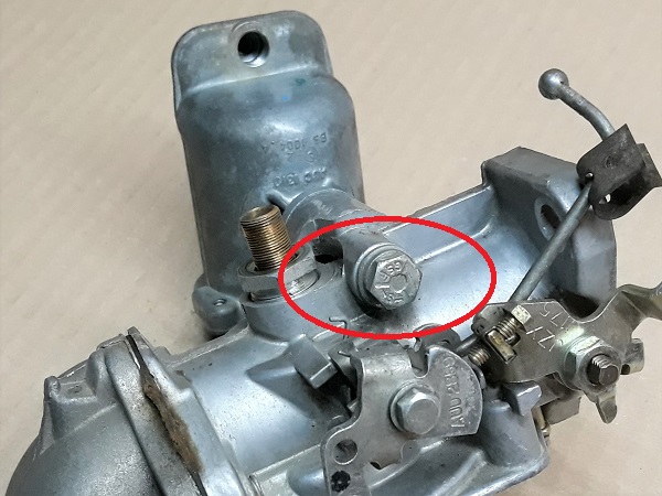
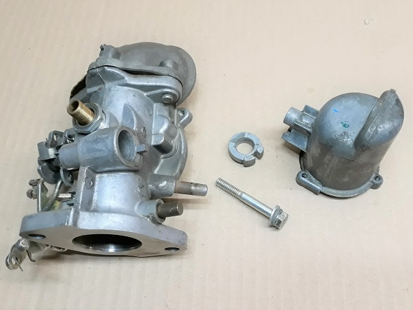
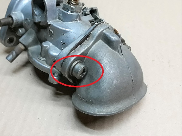
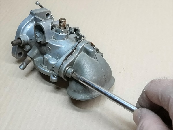
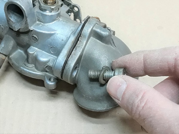
Unscrew the float chamber fixing screw. Use the 11 mm socket spanner.
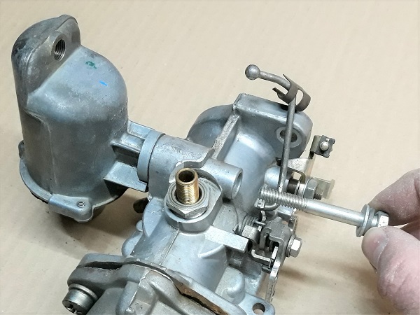
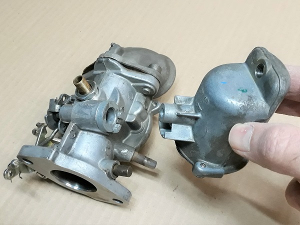
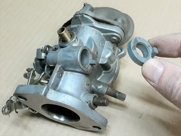
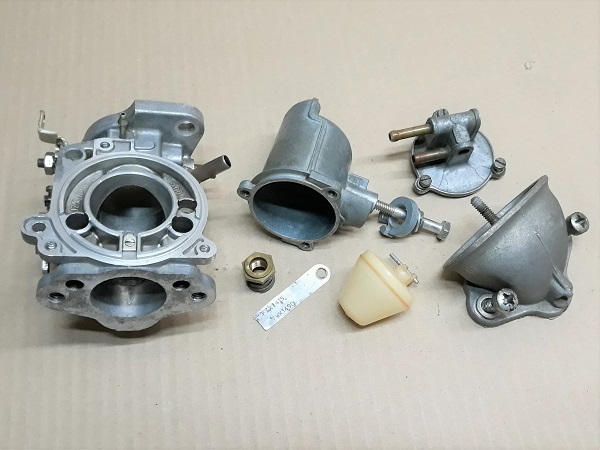
Op 17
Remove the float chamber and its spacer. Pull by hand.
Op 18
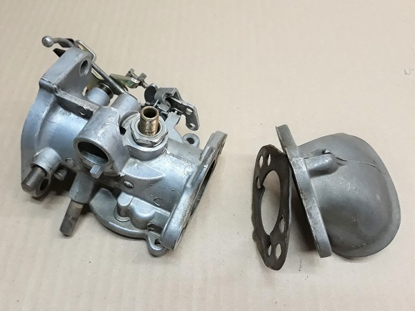
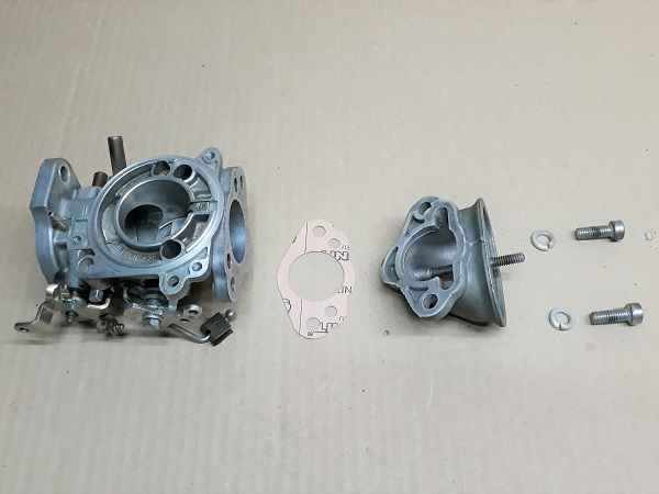
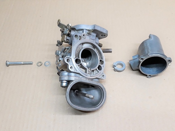
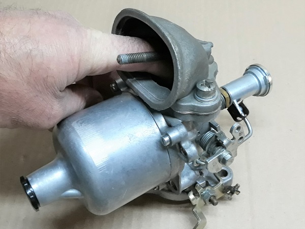
Unscrew the 2 screws securing the air filter elbow. Use the Phillips screwdriver.
Op 19
Remove the air filter elbow and its gasket. Pull by hand.
Advertisement
Rebuild the carburetor
Op 20
Thoroughly clean all the carburetor components. Use gasoline, a brush and a cloth.
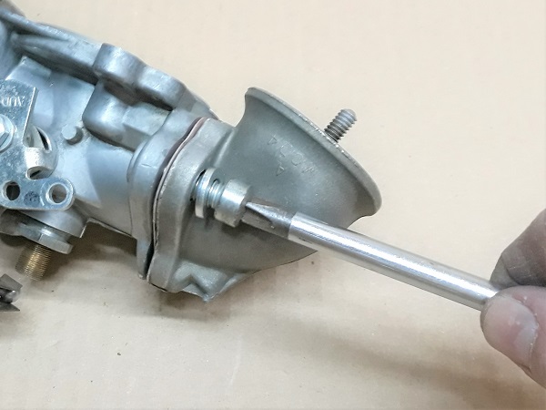
Op 21
Fit the air filter elbow and its gasket (CSK65 kit) on the carburetor body.
Tighten the 2 fixing screws with their washers (GFK1125). Use the Phillips screwdriver.
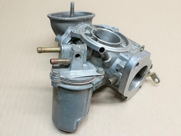
Op 22
Fit the float chamber and its spacer on the carburetor body.
Tighten the float chamber fixing screw with its spring washer (GFK1124) and its flat washer (GFK1113). Use the 11 mm socket spanner.
Op 23
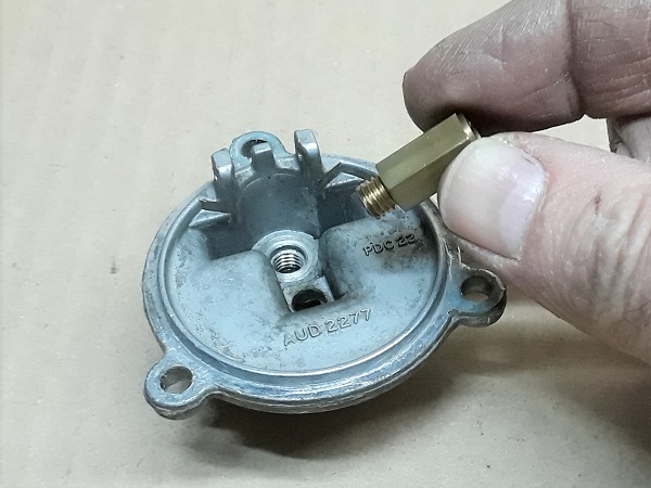
Tighten the needle seat (CSK65 kit). Use a 9 mm socket.
Fit the needle (CSK65 kit). Simply engage it by hand.
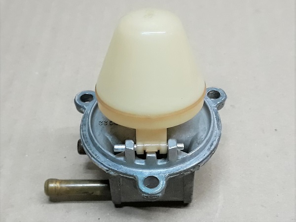
Op 24
Fit the float and engage its pin. Use the pliers.
Engage the non-knurled side of the pin first. The knurls lock the pin on its support.

To make sure the system is working, blow into the petrol inlet pipe and operate the float to check that the inlet is blocked when the float is raised.
Op 25
Fit the cover + float assembly and its gasket (CSK65 kit) on the float chamber.
Tighten the 3 screws with their washers. Use the flathead screwdriver.
Do not forget to position the carburetor number plate on one of the float chamber cover fixing screws.
On my carburetor, I had a flat washer on the screw holding the number plate and spring washers on the other 2 screws. I do not know if it was like that originally or if it had been modified.
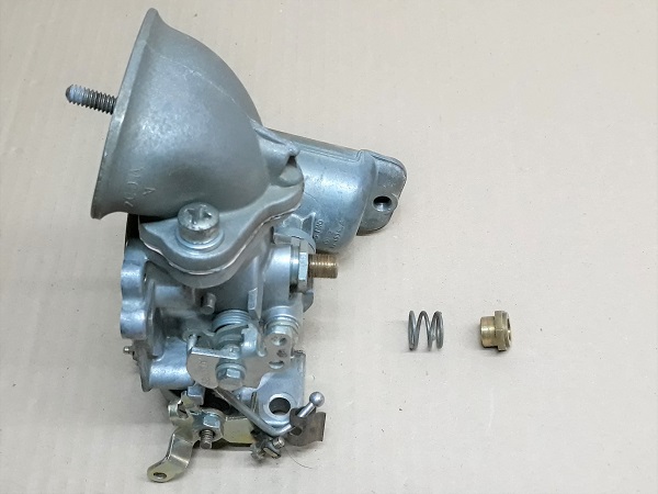
Op 26
Fit the jet locking spring and screw the jet adjusting nut. Screw in by hand.
Tighten the nut until the jet locking spring is completely compressed. Do not force it. We will tune the carburetor later.
Op 27
Fit the jet in its housing. Insert it by hand.
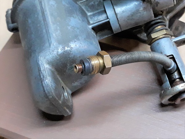
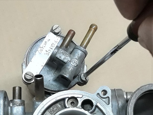
Op 28
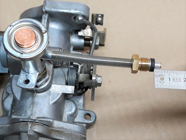
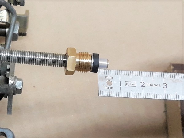
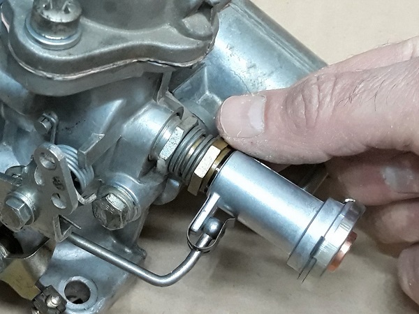
Check that there is a washer and a seal at the end of the jet hose.
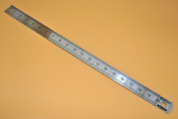
Fit the seal 5 mm from the end of the hose. Use the ruler.
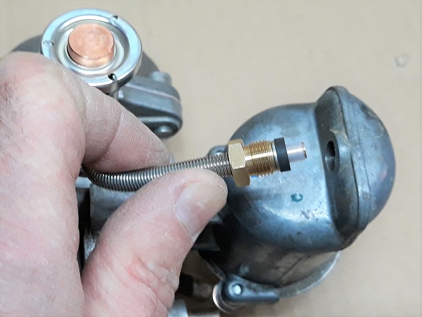
Op 29
Fit the jet hose on the float chamber. Push by hand.
Tighten the nut. Use the 7/16'' spanner.
Op 30
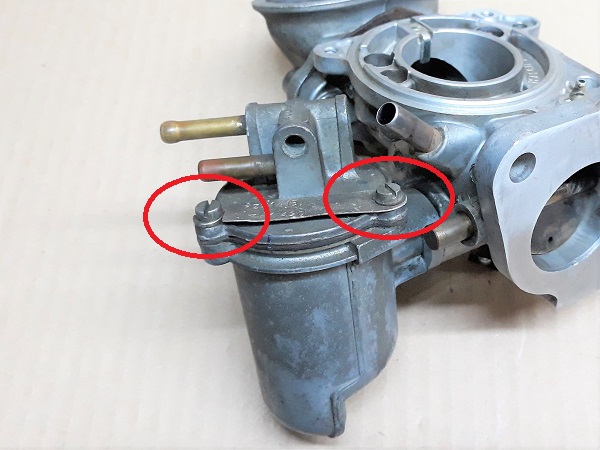
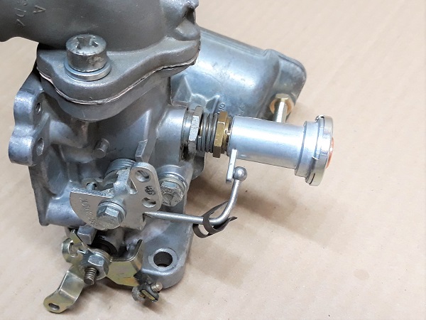
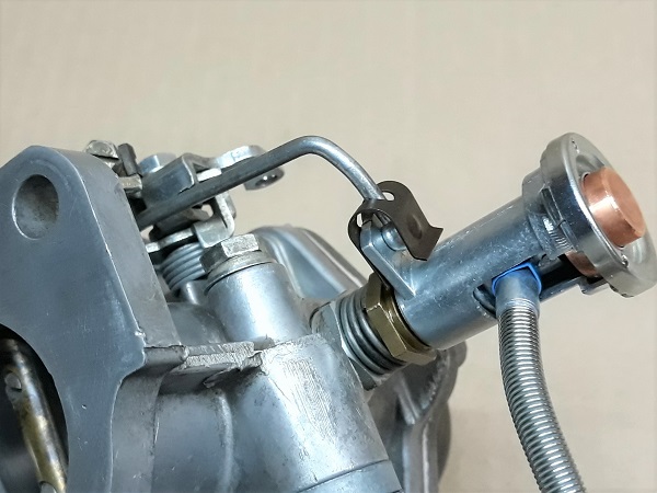
Fit the choke/jet linkage rod on the jet.
Fit the retaining clip. Push with your finger.
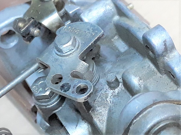
The rod must be positioned below the jet lug (when the carburetor is in a vertical position).
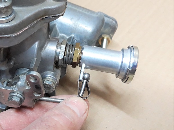
The retaining clip has a mounting direction :
• One end is float chamber-shaped to accommodate the ball of the rod.
• One end has a pin to lock onto the jet lug.
• One end is float chamber-shaped to accommodate the ball of the rod.
• One end has a pin to lock onto the jet lug.
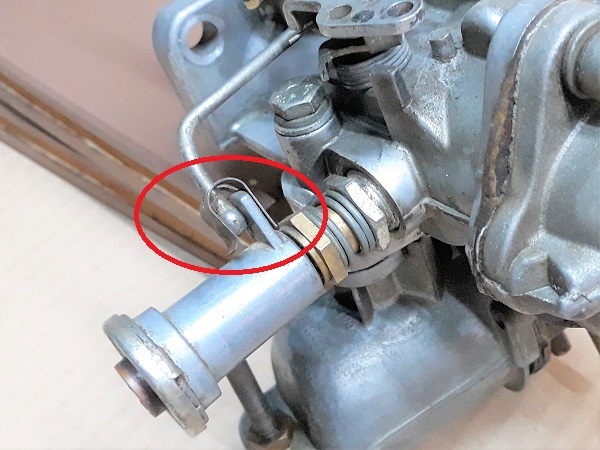
Op 31
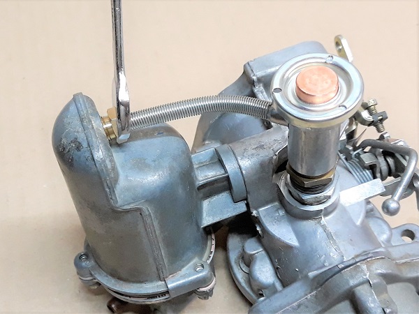
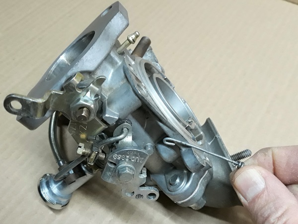
Tension the choke lever return spring. Fit it on its support.
Shape a mini hook out of a wire and use it to pull the spring into the correct position.
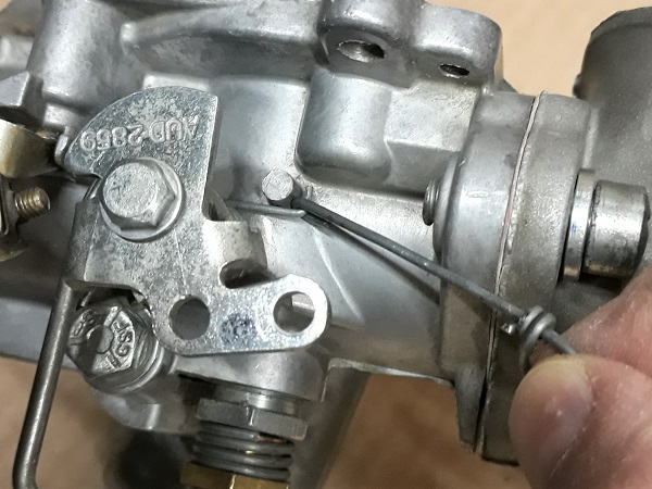
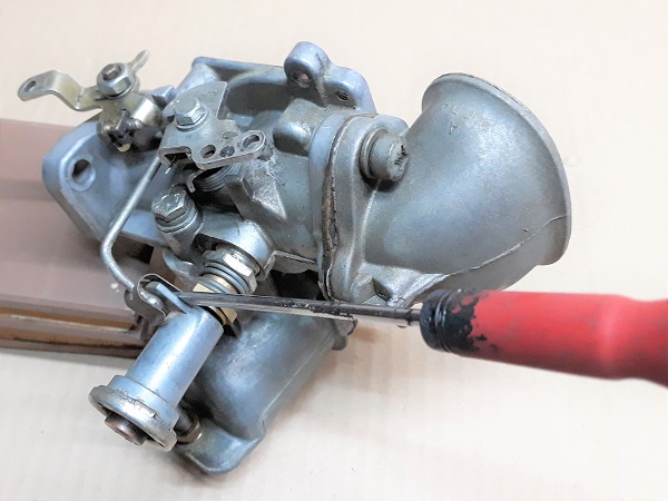
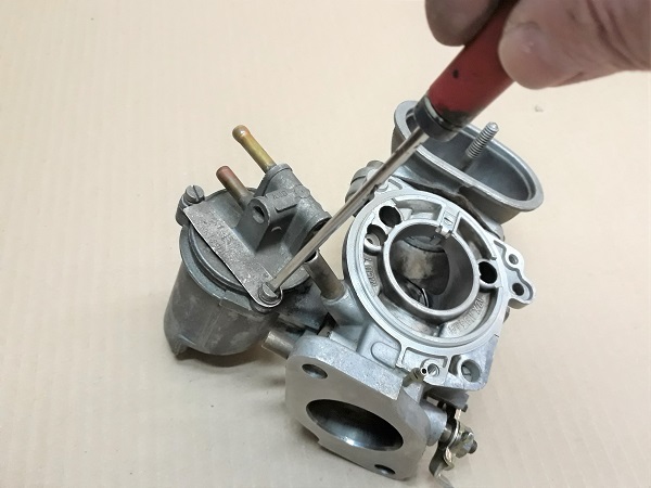
Op 32
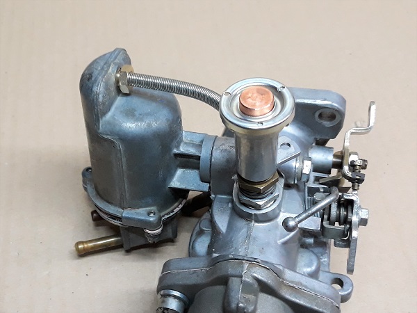
Make sure the choke lever and jet system works well.
The jet should slide freely and return to the stop when the choke control is released.
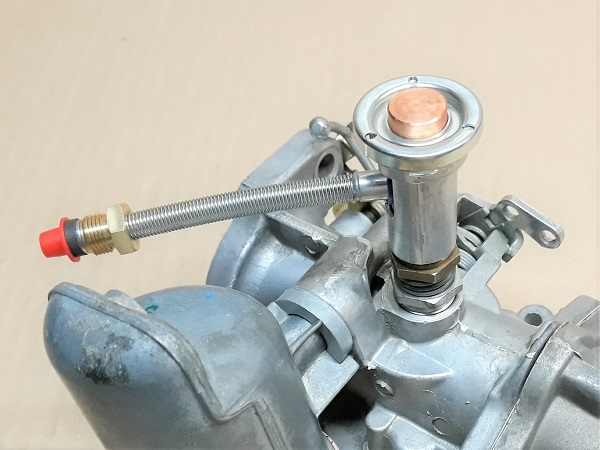
Op 33
Fit the piston + needle assembly.
Fit the piston spring.
Check that the piston + needle assembly slides freely.

Op 34
Fit the dashpot cover and its 3 screws. Use the flathead screwdriver.
Op 35
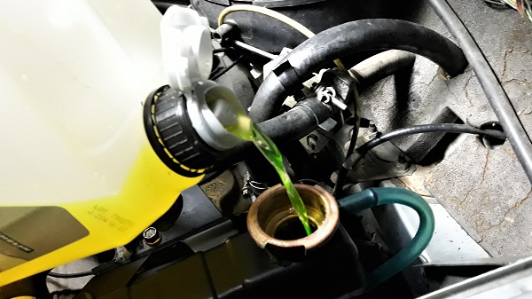
Fit the dashpot damper. Screw in by hand.
The oil will be put in the piston when the carburetor is on the vehicle.
Op 36
Check that the piston slides freely.
When the carburetor is rebuilt, the piston is still accessible by hand through the air filter elbow.
Op 37
Preset the jet adjusting nut. Unscrew the nut by 2 turns.
A tip for counting the 2 turns : just count 12 flats when unscrewing the nut.
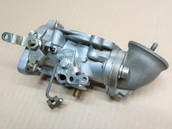
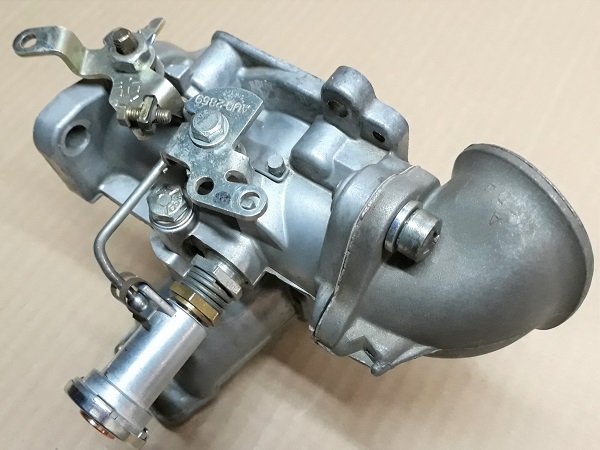
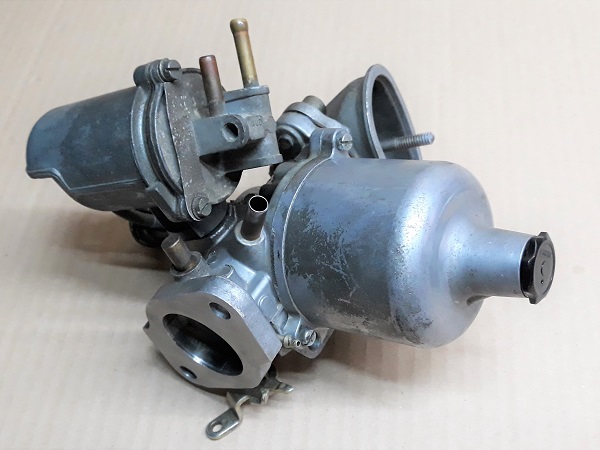
Op 38
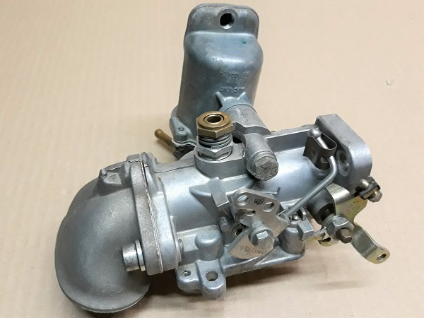
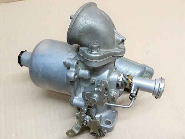
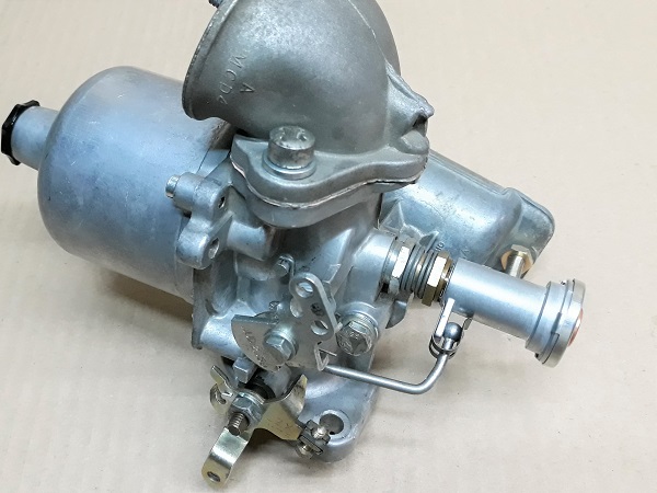
Look at this awesome carburetor. It's like new. Well done ! Excellent work.
Op 39
Fit the carburetor on the Mini (➔ see the tutorial ''HS4 carburetor removal'' Op 13 to 29).
Op 40
Tune the carburetor (➔ see the tutorial ''HS4 carburetor tuning'').
Op 41
Fit the air filter box (➔ see the tutorial ''HS4 air filter change'' Op 10 to 13).
The End