
This tutorial is also available in French
➔

RH differential oil seal change on automatic Austin Mini gearbox
Vehicle ➔ Mini 1000 year 1991 automatic gearbox
Difficulty ➔ Medium

Time ➔ 4 hours
Summary
Advertisement
Advertisement

Recommendations

This tutorial concerns the Mini with an automatic gearbox. For information, the manual gearbox has the same differential oil seals as the automatic gearbox (ADU5738) but the differential side covers are different. The procedure for changing the seals remains the same.
The RH differential output shaft oil seal is on your right when you are sitting in the driver's seat.

Over time, the differential oil seals degrade and the Mini starts to leak oil. This will greatly compromise its chances of passing the next MOT test. It's time to change them.
The size of the automatic gearbox is very different from that of the manual gearbox. The pot joint removing tool (18G1240) is suitable for the manual gearbox. It needs to be slightly modified to be used on the RH output shaft of the automatic gearbox
(➔ see Op 14).
Required Tools
Sponsored links by

Spare Parts
Our Partners


Packaging :
•
All the above parts are sold individually.
Advertisement
Preliminary actions
Op 01
Drain the engine and gearbox (➔ see the tutorial ''Engine + automatic gearbox oil change'' Op 02 to 04).
Op 02
Remove the air filter box (➔ see the tutorial ''HS4 air filter change'' Op 01 to 02).
Op 03
Disconnect the accelerator cable from the carburetor (➔ see the tutorial ''Accelerator cable change'' Op 02 to 04).
Op 04
Remove the carburetor (➔ see the tutorial ''HS4 carburetor removal'' Op 03 to 12).
Op 05
Remove the exhaust system (➔ see the tutorial ''Exhaust system change'' Op 04 to 09).
Op 06
Remove the RH front wheel :
•
Apply the handbrake.
•
Slightly loosen the 4 wheel nuts. Use the 11/16'' socket.
•
Lift the wheel. Use the jack.
•
Fit jack stands or rigid chocks to guarantee your safety.
•
Remove the 4 wheel nuts. Unscrew by hand.
•
Remove the wheel. Pull by hand.
Before working under the vehicle, make sure to secure it properly with jack stands or rigid chocks. Never work under a vehicle supported only by a jack. It is too dangerous.


Remove the swivel hub
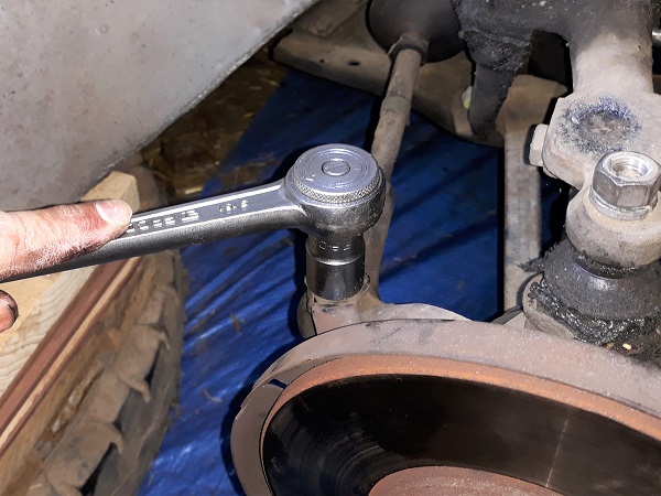
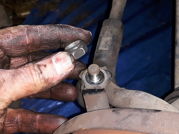
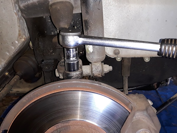
Op 07
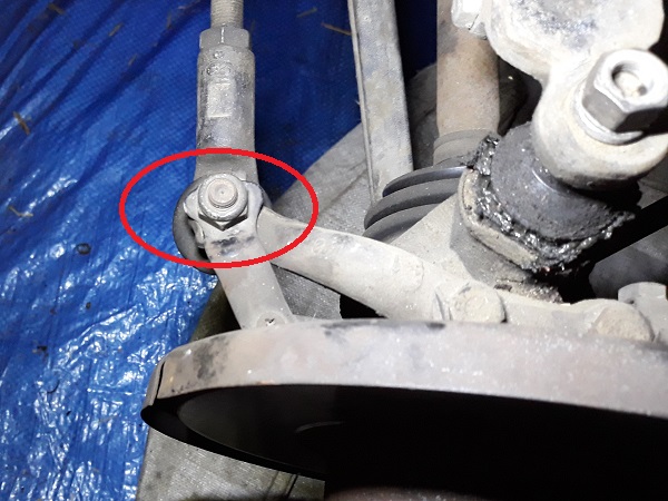
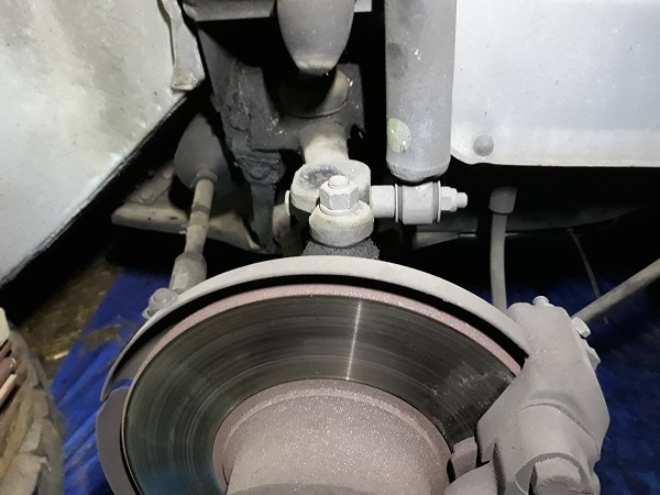
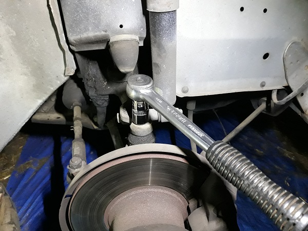
Remove the track rod end fixing nut. Use the 9/16'' socket.
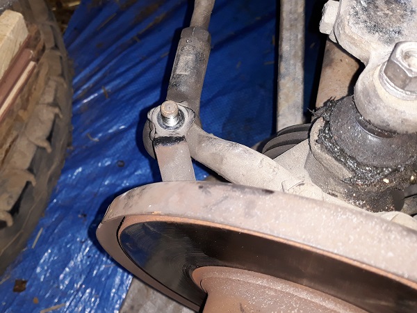
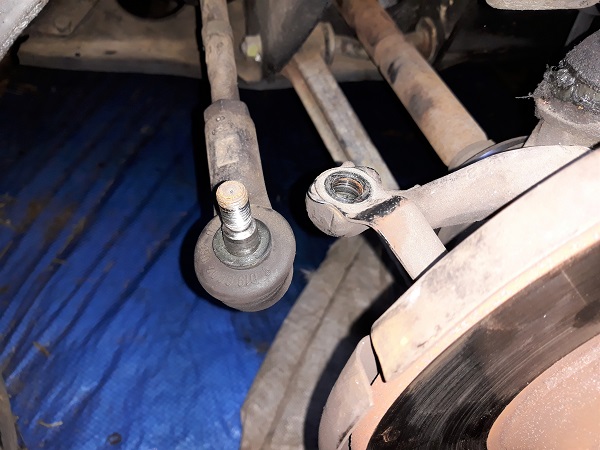
Op 08
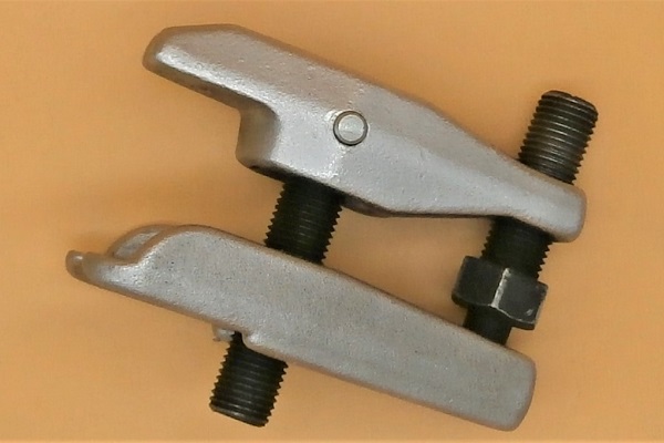
Pull off the track rod end from the steering arm. Use the ball joint puller.

Op 09
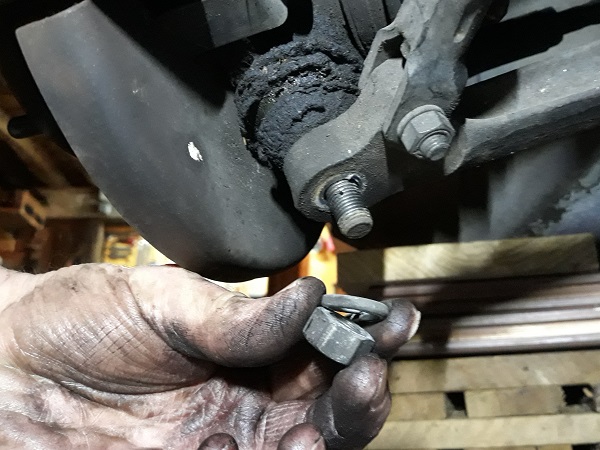
Remove the upper ball joint fixing nut and its washer. Use the 11/16'' socket.

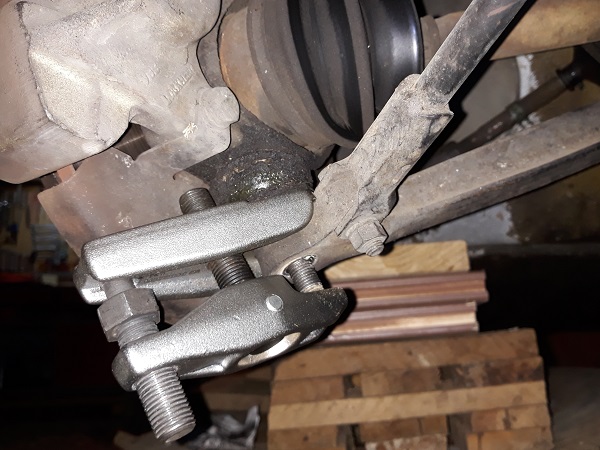
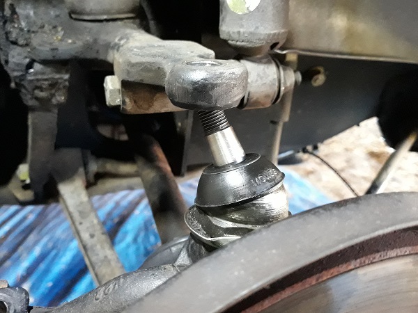
Op 10
Pull off the upper ball joint. Use the ball joint puller.


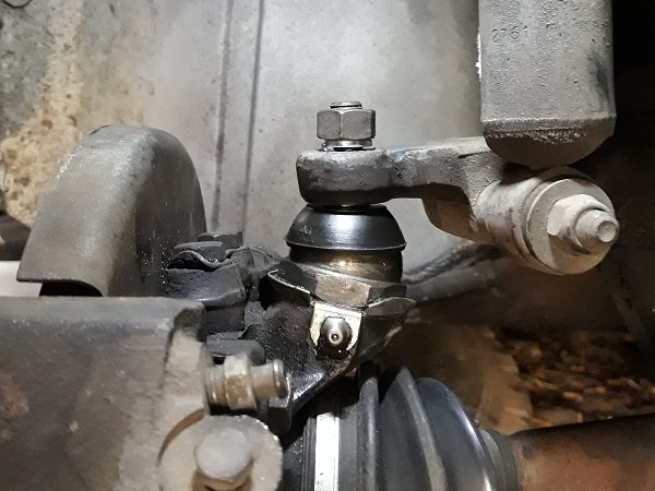
Op 11
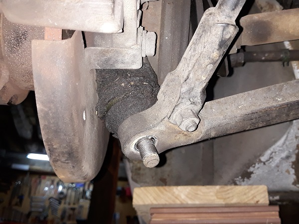
Remove the lower ball joint fixing nut and its washer. Use the 11/16'' socket.
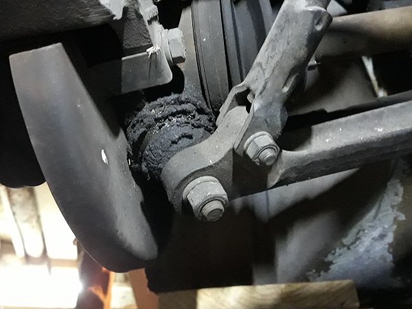
Op 12
Pull off the lower ball joint. Use the ball joint puller.

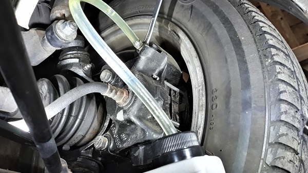
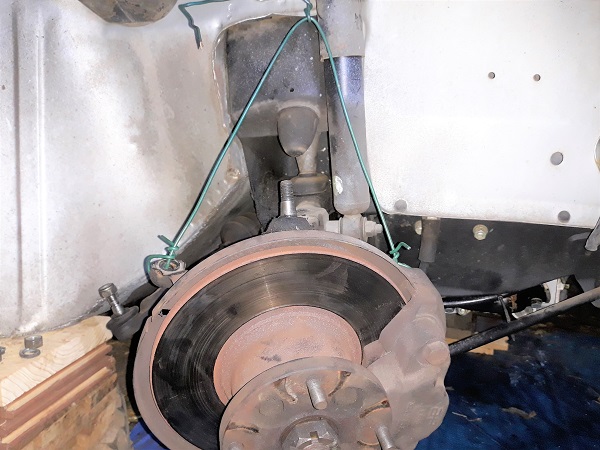
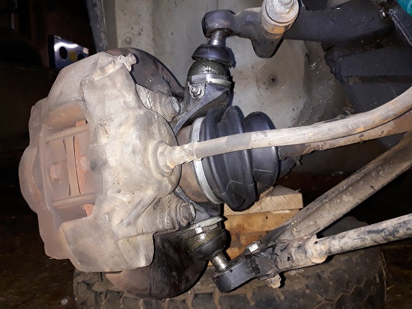
Op 13
Detach the ball joints from the suspension arms and suspend the swivel hub. Use a piece of string or wire.
Be careful not to stretch or damage the brake hose.

Remove the oil seal
Op 14
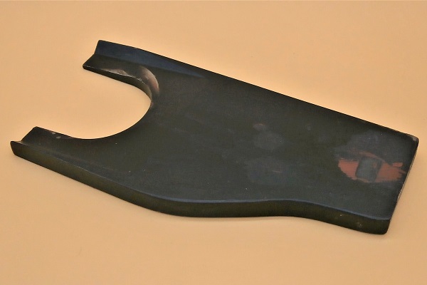
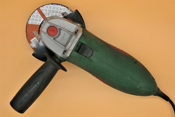
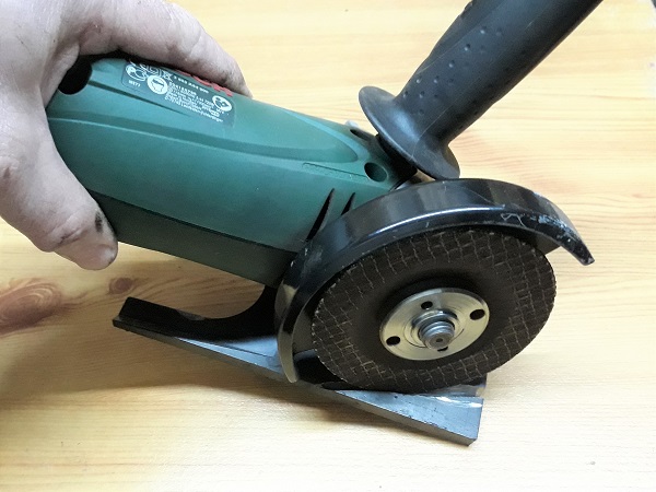
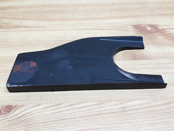
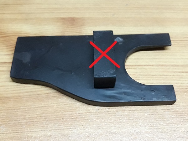
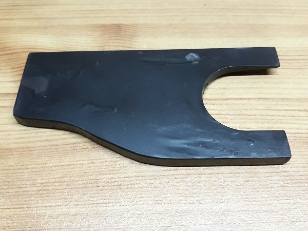
Modify the pot joint removing tool (18G1240).
Cut along the green lines (1st photo) and remove the shim located at the rear. Use an angle grinder.
The removing tool is designed to detach the pot joints from the manual gearbox. It must be slightly notched and shortened to extract the RH pot joint from the automatic gearbox.

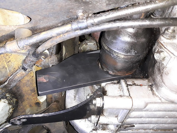
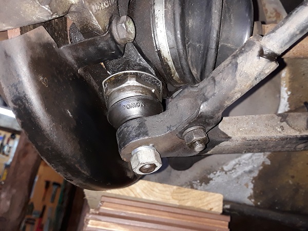
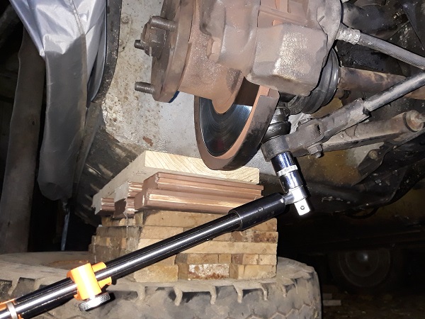
Op 15
Detach the pot joint from the gearbox :
•
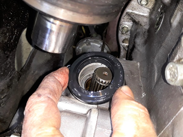
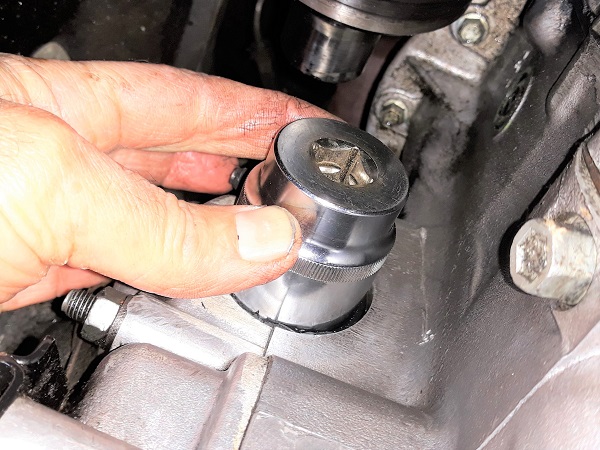
Slide the removing tool between the pot joint and the gearbox casing (1st photo).
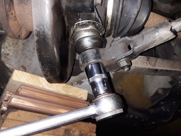
•
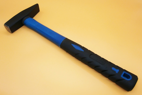
Tap the removing tool with the hammer until the pot joint comes loose (2nd photo).
The pot joint is only held in place by a metal clip. It will resist as the removing tool advances and it will suddenly come loose.
If you don't have a removing tool, you can detach the pot joint with 2 tire levers by levering between the pot joint and the gearbox. Position the 2 tire levers symmetrically on either side of the pot joint. If you only use one tire lever or if you are not perfectly symmetrical, the pot joint will be slightly skewed, it will lock and it will not come out.


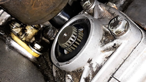
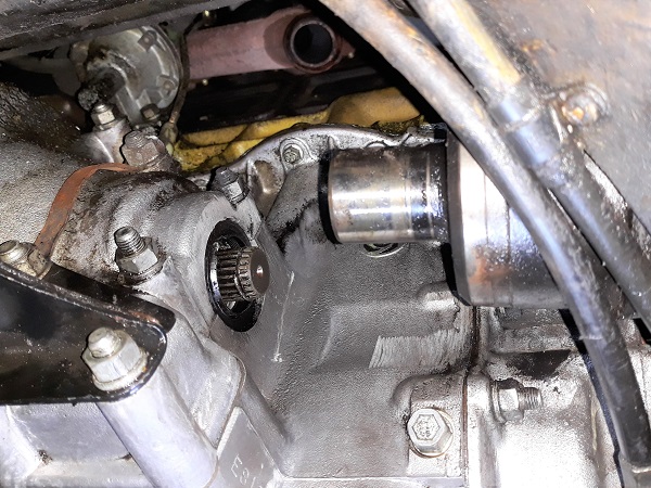
Op 16
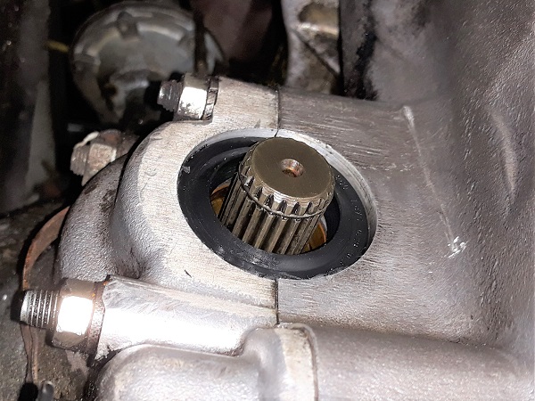
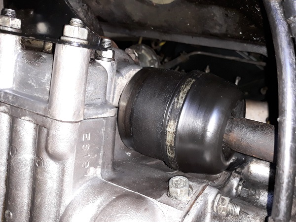
Extract the pot joint from the gearbox. Pull sideways by hand.
Suspend the pot joint to clear access to the oil seal. Use a piece of string.

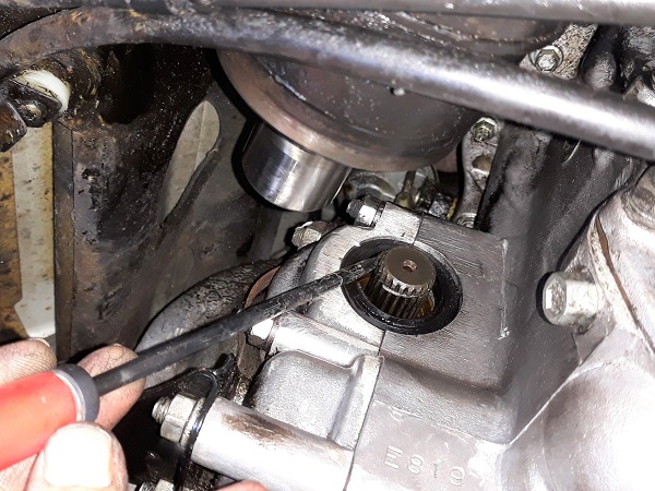
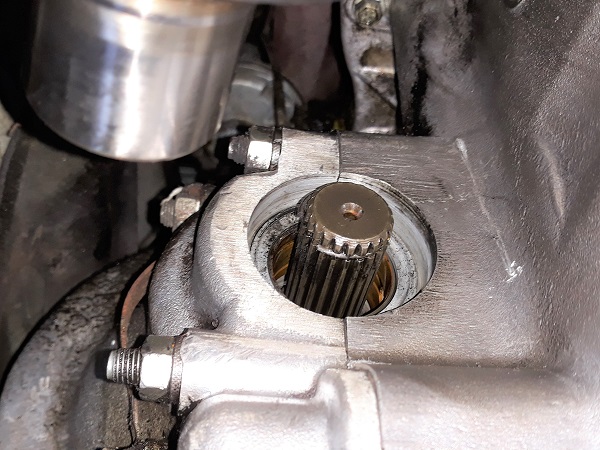
Op 17
Remove the oil seal. Use a flathead screwdriver.
Be careful not to scratch the aluminum casing of the differential with the screwdriver.

Advertisement
Fit the oil seal
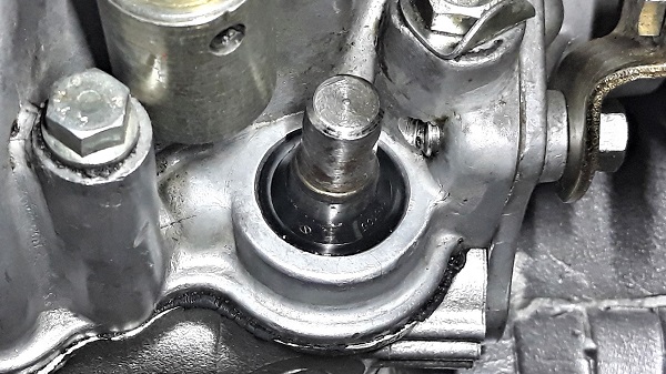
Op 18
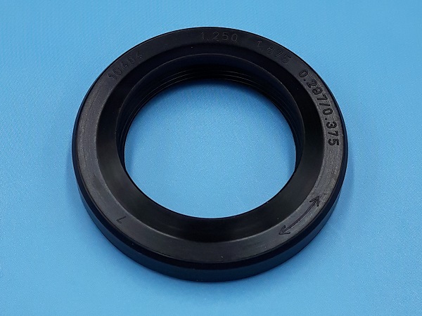
Oil or grease the lip of the new oil seal (ADU5738).

Op 19
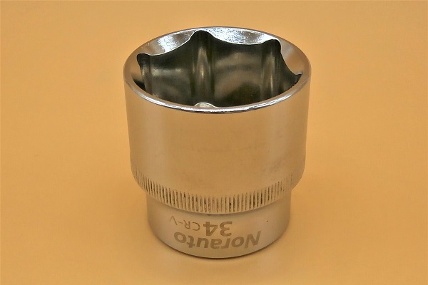
Fit the new oil seal. Use a 34 mm socket and tap with a hammer.
The 34 mm socket allows you to press evenly over the entire surface of the seal. You can hit the socket with the hammer without risk of damaging the seal.
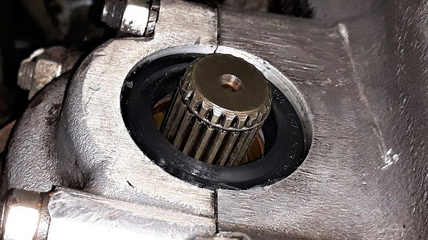
Op 20
Fit the pot joint in its housing. Push firmly by hand.
Recenter the clip in its groove before engaging the pot joint on the splined shaft.
Be careful not to damage the lip of the oil seal when you engage the pot joint, otherwise all your efforts to stop oil leaks will be reduced to nothing.
You will hear a very slight ''click'' when the pot joint is locked (the clip will then have found its place).


Fit the swivel hub
Op 21
Fit the 2 ball joints on the suspension arms.

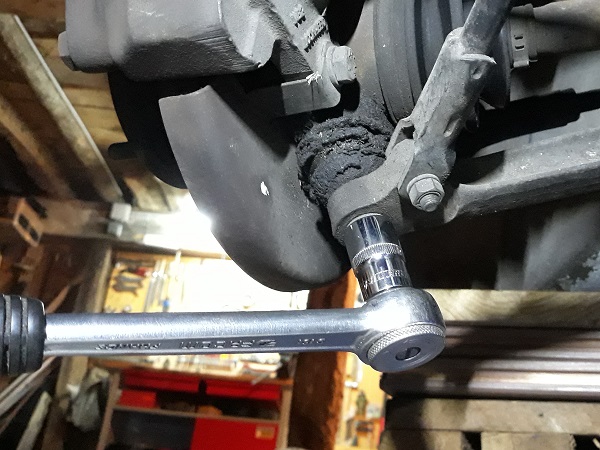
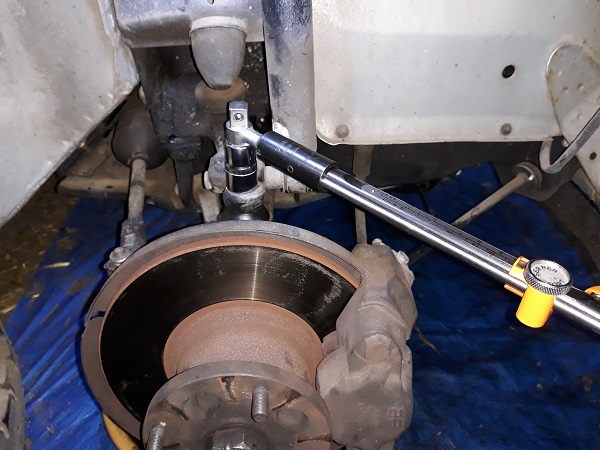
Op 22
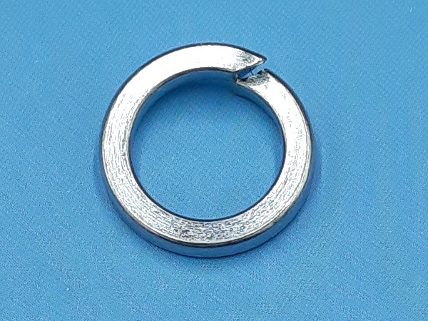
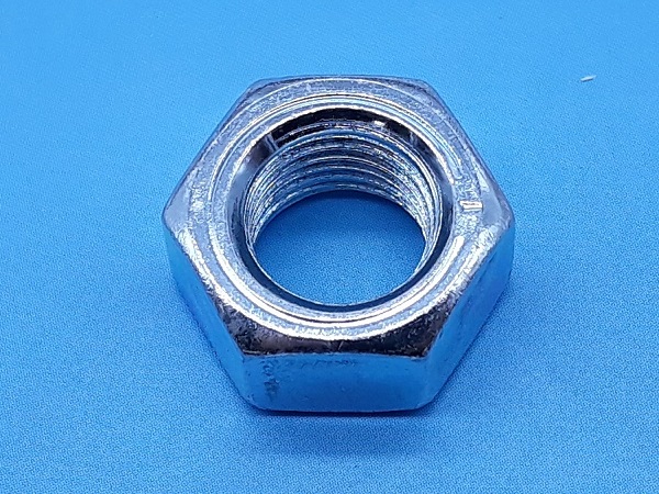
Fit a new spring washer (GFK1127) and screw on the lower ball joint fixing nut (GFK3214). Use an 11/16'' socket.
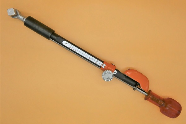
Tighten to a torque of 52 mN. Use a torque wrench.
Op 23
Fit a new spring washer (GFK1127) and screw on the upper ball joint fixing nut (GFK3214). Use an 11/16'' socket.
Tighten to a torque of 52 mN. Use a torque wrench.
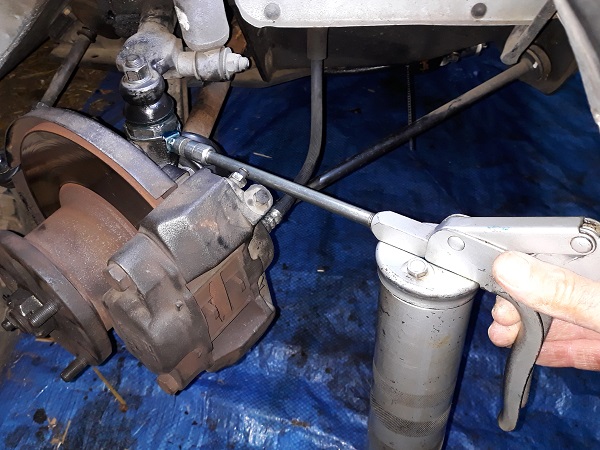
Op 24
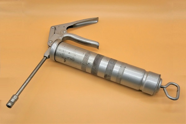
Grease the 2 ball joints. Use a grease gun.
While the track rod end is still separated from the steering arm, take the opportunity to grease the ball joints. It's much easier.
Do not hesitate to rotate the swivel hub so that the grease can penetrate and be well distributed in the ball joints.


Op 25
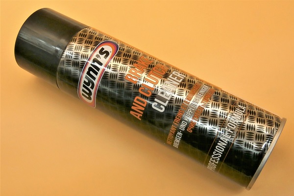
Clean the brake disc. Remove any traces of grease. Use brake cleaner and a cloth.

Op 26
Fit the axis of the track rod end in the steering arm.
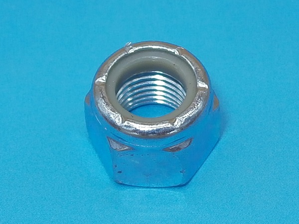
Screw on the track rod end nut (GFK3323). Use the 9/16'' socket.
Tighten the nut to a torque of 30 mN. Use the torque wrench.


Advertisement
Final actions
Op 27
Fit the RH front wheel :
•
Fit the wheel on the drive flange.
•
Screw on the 4 nuts. Use the 11/16'' socket.
•
Lower the Mini to the ground. Remove the jack stands.
•
Tighten the 4 nuts to the torque corresponding to the type of rim. Use the torque wrench.
The tightening torque of the wheel nuts is :
• 63 mN for steel rims.
• 50 mN for alloy rims.
• 63 mN for steel rims.
• 50 mN for alloy rims.
Op 28
Fit the exhaust system (➔ see the tutorial ''Exhaust system change'' Op 17 to 31).
Op 29
Fit the carburetor (➔ see the tutorial ''HS4 carburetor removal'' Op 13 to 26).
Op 30
Connect the accelerator cable to the carburetor (➔ see the tutorial ''Accelerator cable change'' Op 30 to 34).
Op 31
Check the carburetor oil level (➔ see the tutorial ''HS4 carburetor removal'' Op 28 and 29).
Op 32
Fit the air filter box (➔ see the tutorial ''HS4 air filter change'' Op 10 to 13).
Op 33
Add oil to the engine and gearbox (➔ see the tutorial ''Engine + automatic gearbox oil change'' Op 16 to 21).
The End