
This tutorial is also available in French
➔

Valve clearance adjustment on Austin Mini
Vehicle ➔ Mini 1000 year 1991 automatic gearbox
Difficulty ➔ Medium

Time ➔ 2 hours
Summary
Advertisement
Advertisement

Recommendations

When a valve is closed, there is clearance between the valve stem and its rocker arm. This clearance is necessary because the component parts of the engine expand when the temperature increases. This clearance ensures that the valve will always be properly closed regardless of the engine temperature.

If the clearance of a valve is too small, the valve will not close properly. The edge of the valve and its seat may burn.
Adjusting the valve clearance must be done when the engine is cold.
Adjusting the valve clearance requires turning the crankshaft very precisely to open each of the valves in turn. On a Mini with an automatic gearbox, the method of turning one of the front wheels does not work. The correct method is to remove the small rubber grommet located above the torque converter housing to free access to the starter motor ring gear. Then simply lever the ring gear teeth with a flathead screwdriver and thus turn the crankshaft. It's tedious but it works.
During various manipulations, always turn the crankshaft in the direction of engine rotation. This allows you to take up the slack.
Required Tools
Sponsored links by

Advertisement
Access the crankshaft on a Mini automatic gearbox
Op 01
Remove the air filter box (➔ see the tutorial ''HS4 air filter change'' Op 01 to 02).
Op 02
Remove the rocker cover (➔ see the tutorial ''Rocker cover gasket change'' Op 02 to 04).
Op 03
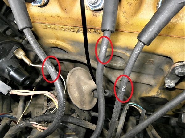
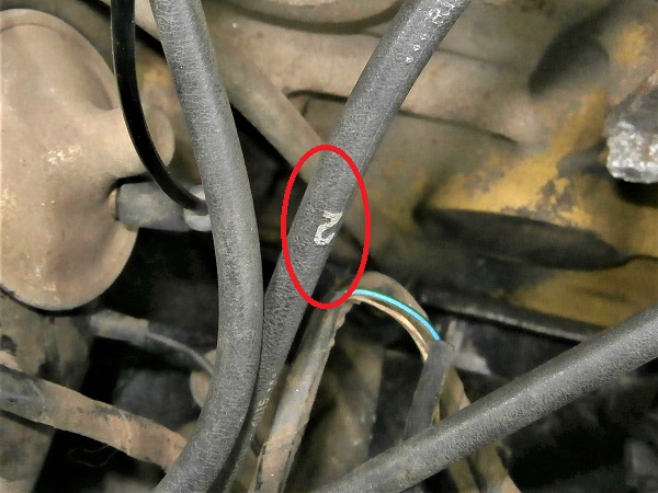
Check that the spark plug ignition wires are properly identified. Otherwise, write the corresponding spark plug number on each of the 4 ignition wires.
The spark plugs are generally numbered from 1 to 4 starting with the spark plug closest to the radiator.
Identifying the ignition wires will make things easier during reassembly.
Op 04
Remove the 4 spark plugs (➔ see the tutorial ''Spark plugs change'' Op 01 to 02).
Op 05
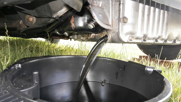
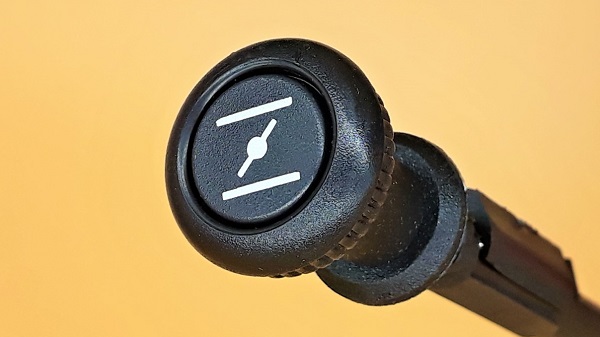
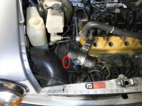
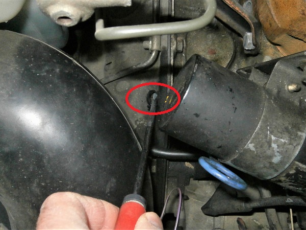
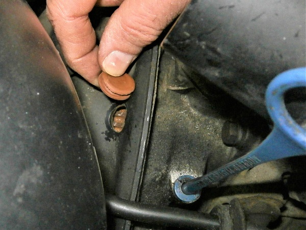
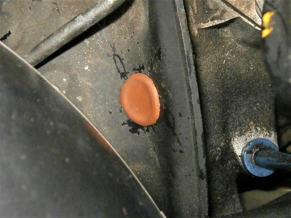
Locate where the small rubber plug of the torque converter housing is.
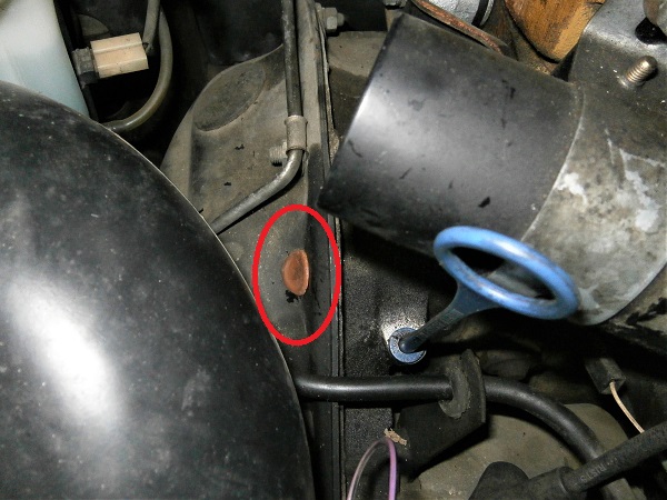
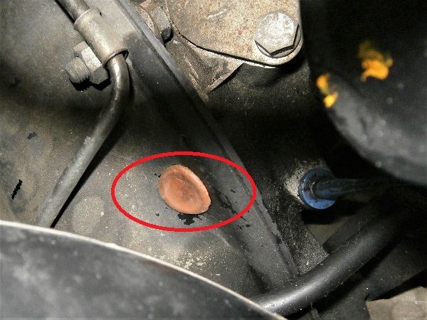
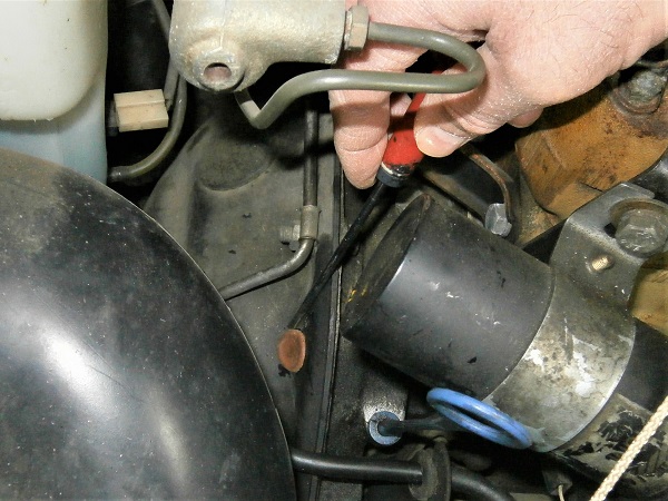
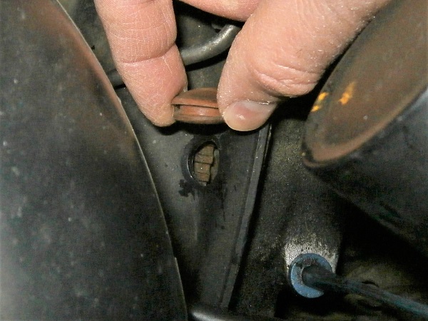
Op 06
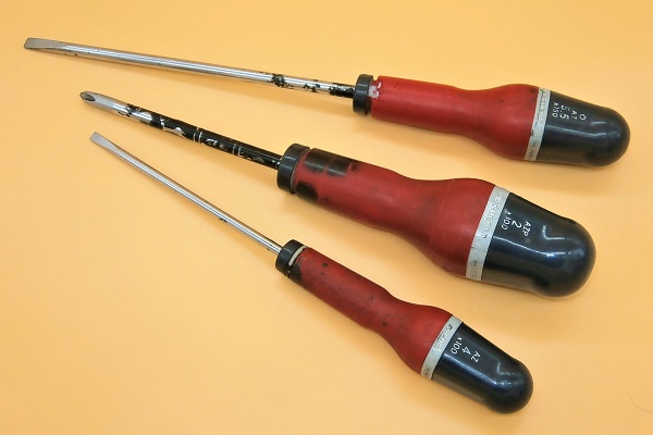
Remove the small rubber plug from the torque converter housing. Use the small flathead screwdriver.
The teeth of the starter motor ring gear can be seen. This is what will allow us to turn the crankshaft.
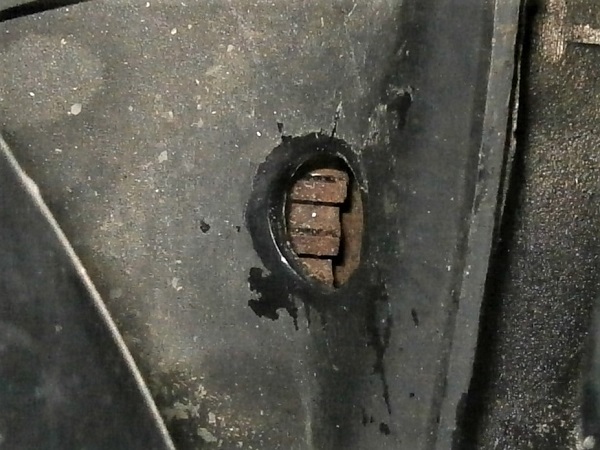
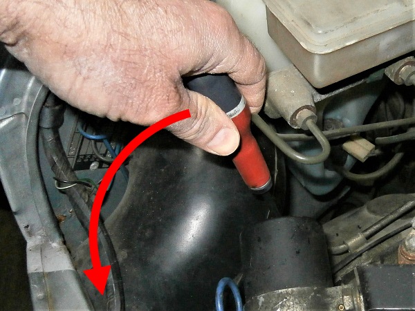
Op 07
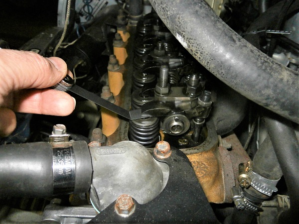
Insert the large flathead screwdriver into the torque converter housing orifice.
Check that the crankshaft turns when levering on the teeth of the starter motor ring gear.
Yes, it's tedious to say the least. But I warned you.
Advertisement
Adjust valve clearance
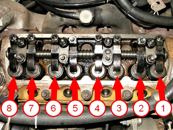
Op 08
Identify the number of each of the 8 valves.
Valve number 1 is located on the radiator side.
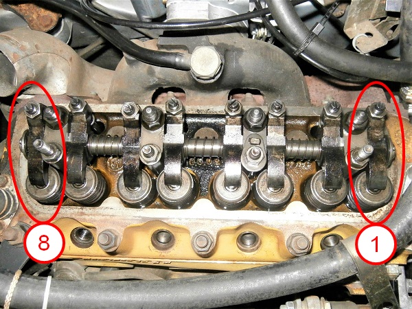
Op 09
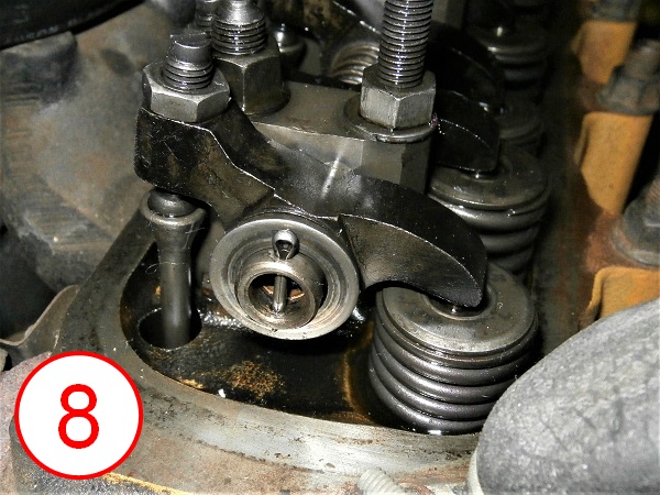
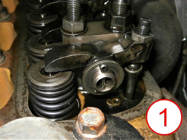
Turn the crankshaft slowly to bring valve #8 to the maximum open position. Use the large flathead screwdriver.
You can see in the photos that valve #8 is fully depressed and the rocker arm of valve #1 is horizontal.
Op 10
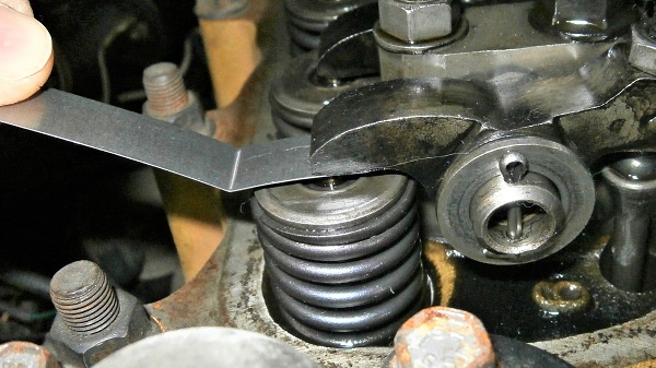
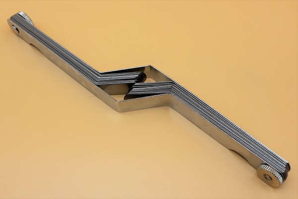
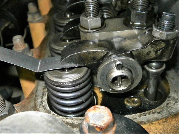
Check that the 0.3 mm feeler gauge passes between valve #1 and its rocker arm.
The feeler gauge should slide ''smoothly''.
Op 11
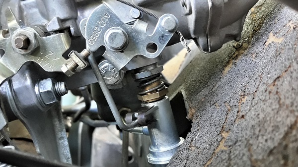
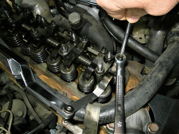
If the clearance is not correct (too much or not enough clearance), adjust as follows :
•
Hold the rocker arm adjusting screw to prevent it from turning. Use the large flathead screwdriver.
•
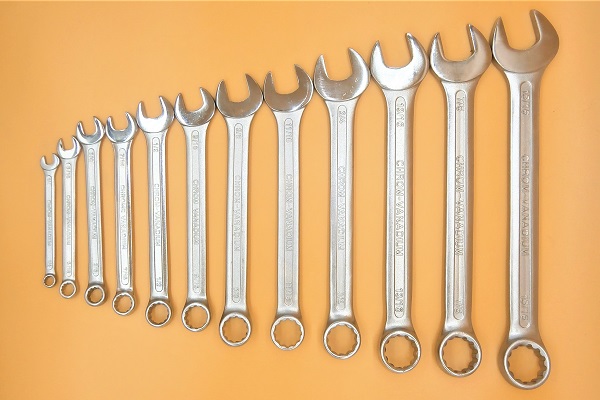
Slightly loosen the rocker arm adjusting nut. Use the 1/2'' spanner.
•
Slightly loosen the screw (only if there is not enough clearance).
•
Position the 0.3 mm feeler gauge between the valve and its rocker arm.
•
Turn the screw to adjust the clearance. The gauge should slide ''smoothly''.
•
Tighten the nut while holding the screw to prevent it from rotating.
•
Screwing the rocker arm adjusting screw reduces the clearance.
• Unscrewing the screw increases the clearance.
• Unscrewing the screw increases the clearance.
Once the nut is tightened, do not hesitate to make a final check of the clearance. The screw may have turned slightly when tightening the nut. You never know.

Op 12
All that remains is to adjust the other 7 valves by repeating Op 09, 10 and 11.
Nevertheless, the following order must be respected :
• Open #6 and adjust #3
• Open #4 and adjust #5
• Open #7 and adjust #2
• Open #1 and adjust #8
• Open #3 and adjust #6
• Open #5 and adjust #4
• Open #2 and adjust #7
• Open #6 and adjust #3
• Open #4 and adjust #5
• Open #7 and adjust #2
• Open #1 and adjust #8
• Open #3 and adjust #6
• Open #5 and adjust #4
• Open #2 and adjust #7
Op 13
Fit the small rubber plug in the torque converter housing.
Op 14
Fit the 4 spark plugs and connect their ignition wires (➔ see the tutorial ''Spark plugs change'' Op 03 to 05).
This is when identifying the ignition wires becomes very useful.
Op 15
Fit the rocker cover (➔ see the tutorial ''Rocker cover gasket change'' Op 09 to 15).
Op 16
Fit the air filter box (➔ see the tutorial ''HS4 air filter change'' Op 10 to 13).
The End