
This tutorial is also available in French
➔

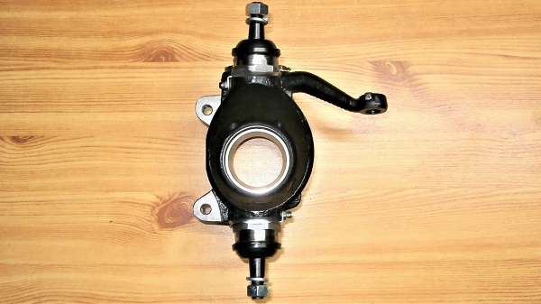
Swivel hub ball joints change on Austin Mini
Vehicle ➔ Mini 1000 year 1988
Difficulty ➔ Medium
Time ➔ 4 hours
Summary
Advertisement
Advertisement

Recommendations

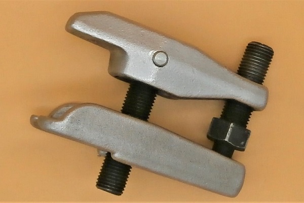
Use a very good quality ball joint puller to remove the ball joints because the force required is very important. If you break your ball joint puller, do not hesitate to invest in a better quality tool.
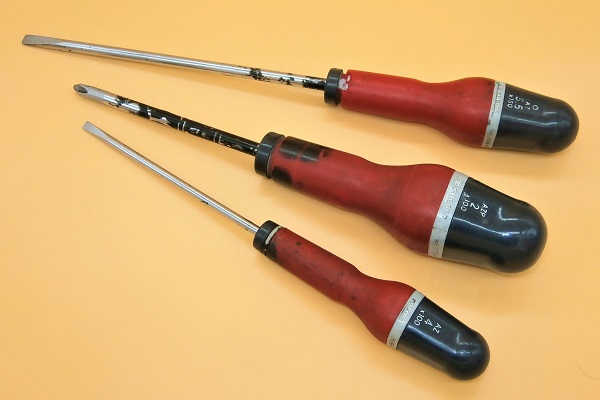
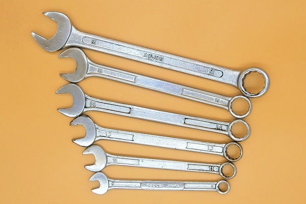
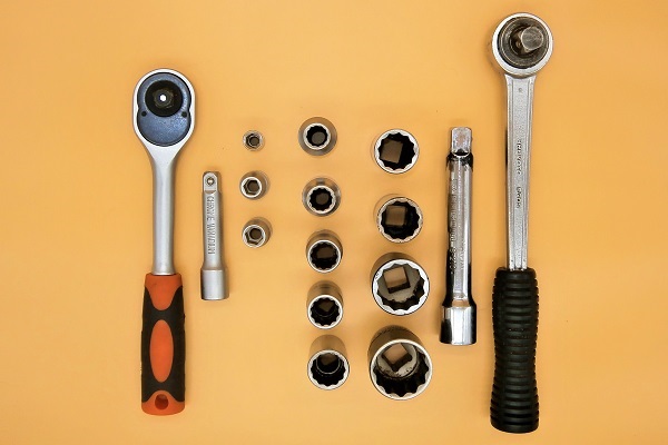
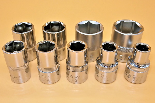
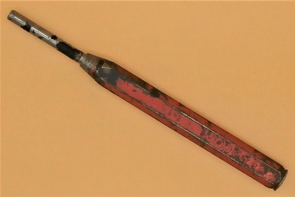
Required Tools
Sponsored links by

Spare Parts
Our Partners


Packaging :
•
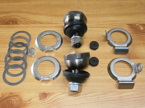
GSJ166MS : Ball joint kit for 1 swivel hub (2 ball joints + 2 seats + 1 spring + 2 locking washers + 1 assortment of shims).
• The other parts above are sold individually.
• The other parts above are sold individually.
Advertisement
Remove the swivel hub
Op 01
Remove the wheel and the brake pads (➔ see the tutorial ''Front brake pads change'' Op 01 to 06).
Op 02
Remove the caliper, the brake disc and the drive flange (➔ see the tutorial ''Front brake discs change'' Op 02 to 07).
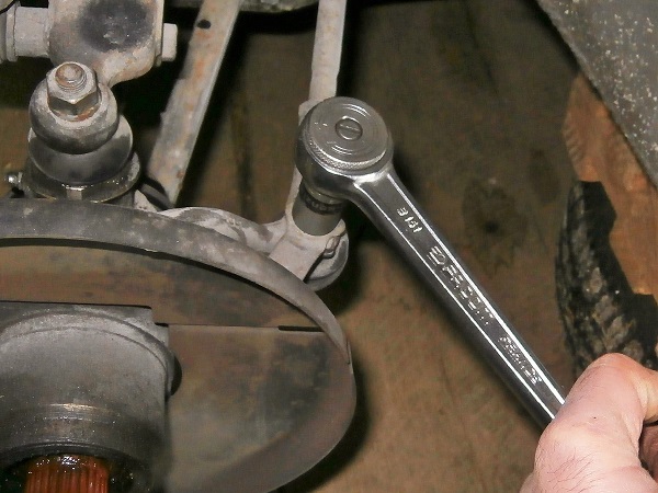
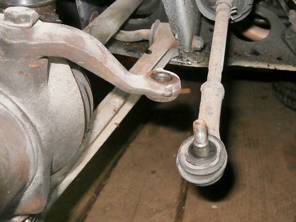
Op 03
Remove the track rod end fixing nut. Use the 9/16'' socket.
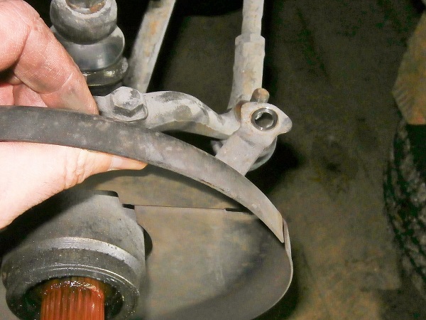
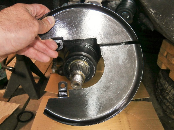
Op 04
Remove the brake disc shield (the plate that protects the disc).
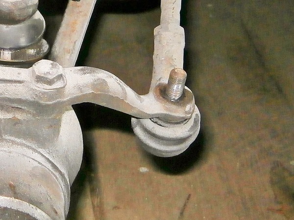
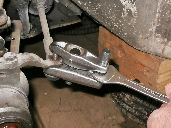
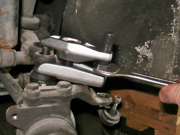
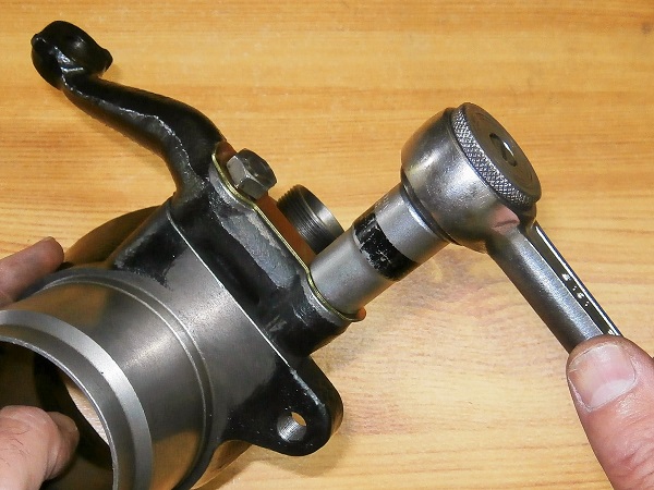
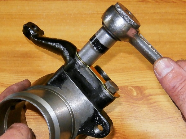
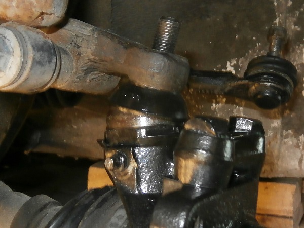
Op 05
Pull off the track rod end from the steering arm. Use the ball joint puller.
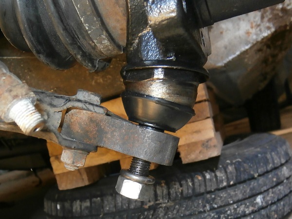
Op 06
Remove the upper ball joint fixing nut and its washer. Use the 11/16'' socket.
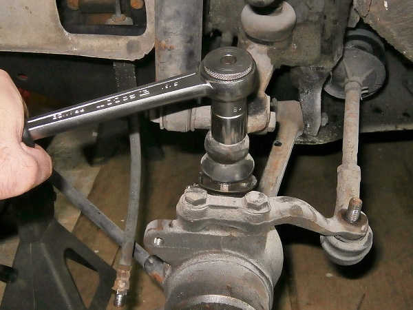
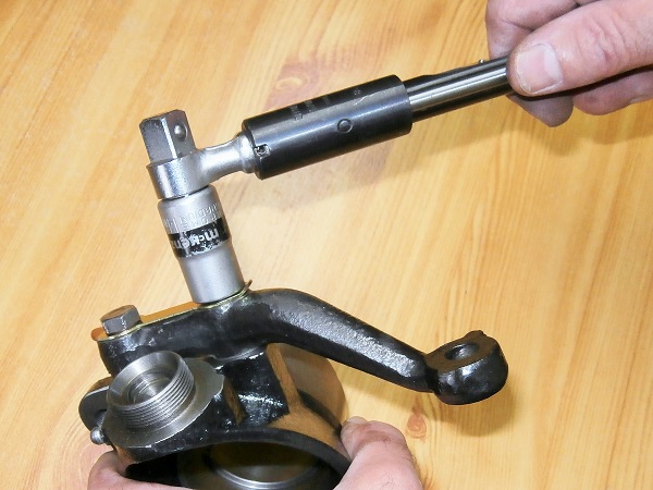
Op 07
Pull off the upper ball joint. Use the ball joint puller.
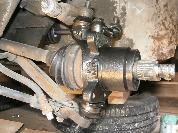
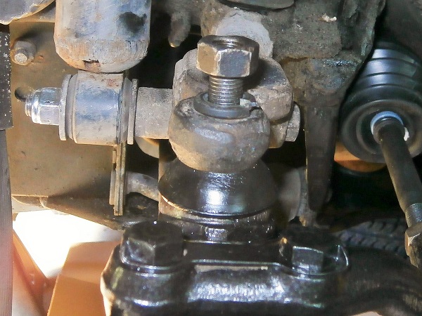
Op 08
Remove the lower ball joint fixing nut and its washer. Use the 11/16'' socket.
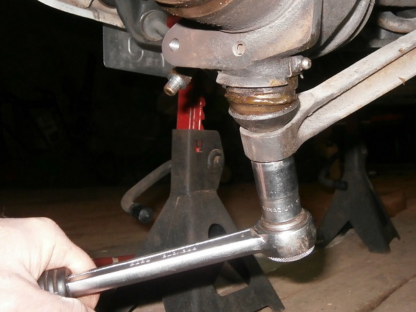
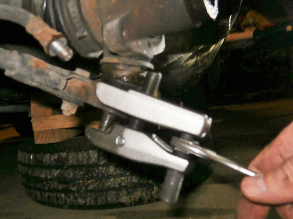
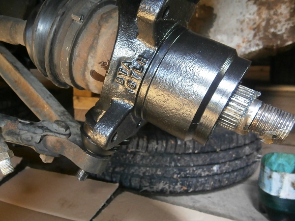
Op 09
Pull off the lower ball joint. Use the ball joint puller.
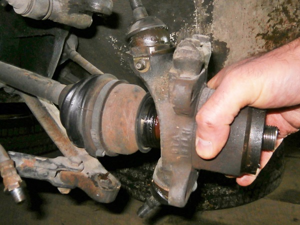
Op 10
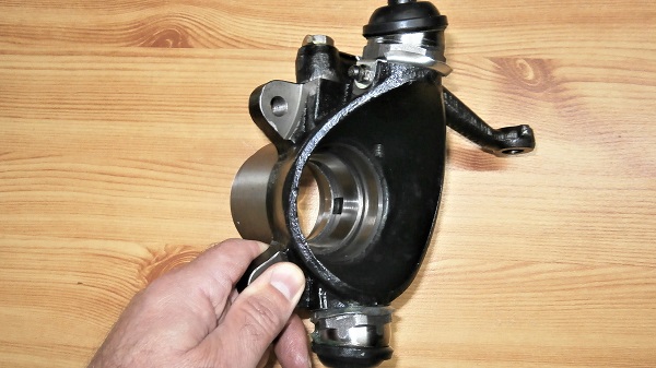
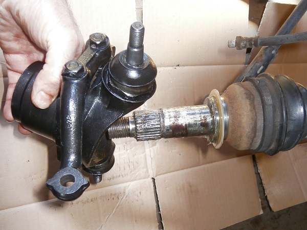
Remove the front swivel hub. Pull by hand.
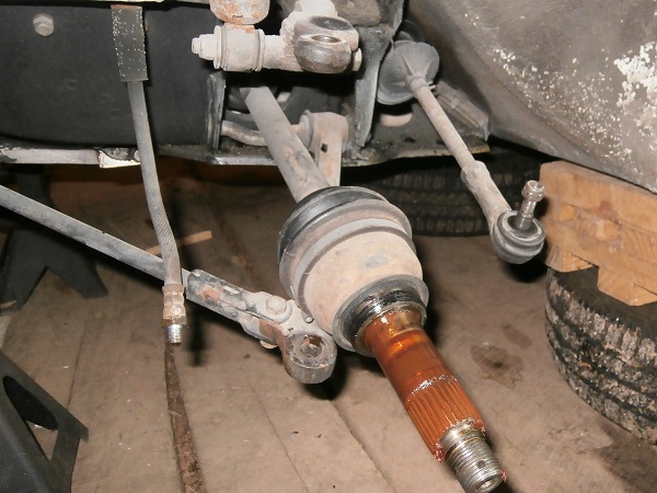
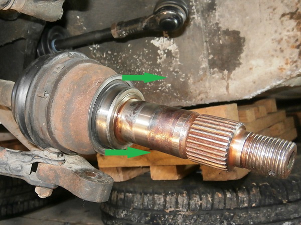
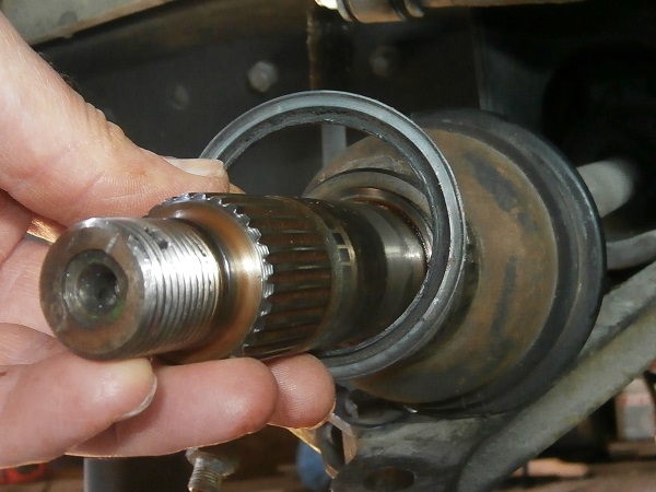
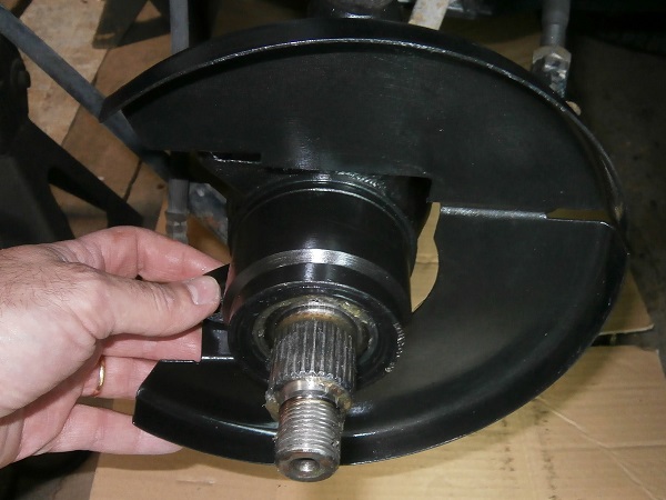
Op 11
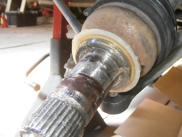
Remove the water shield from the CV joint shaft. Pull by hand.
Remove the ball joints
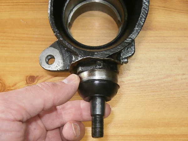
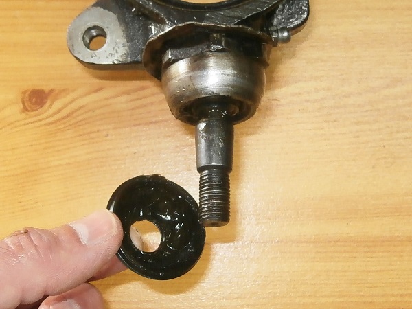
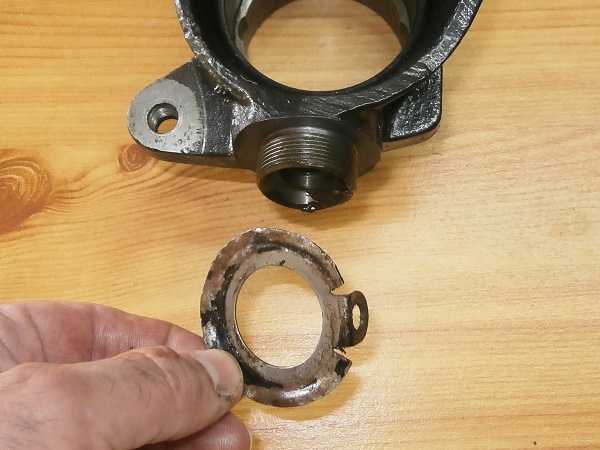
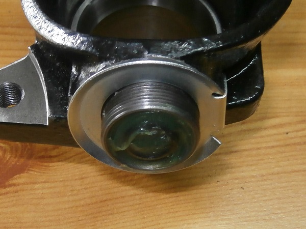
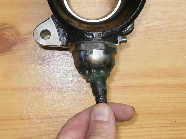
Op 12
Remove the dust cover from the lower ball joint.
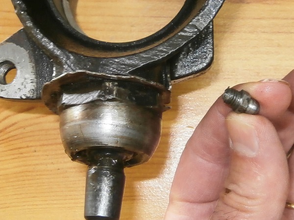
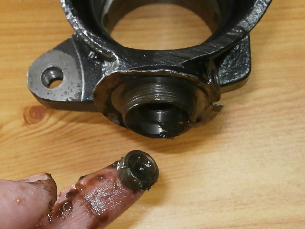
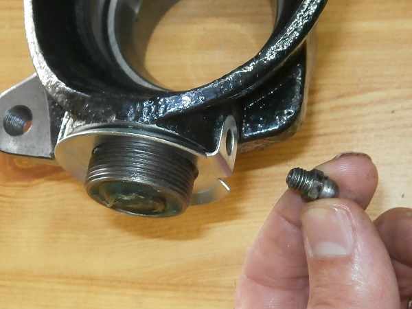
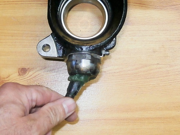
Op 13
Remove the grease nipple. Use the 8 mm spanner.
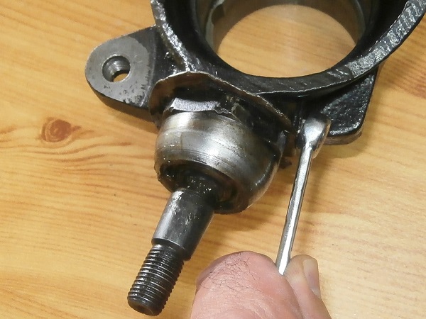
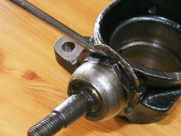
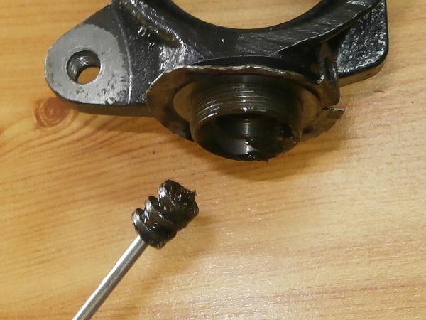
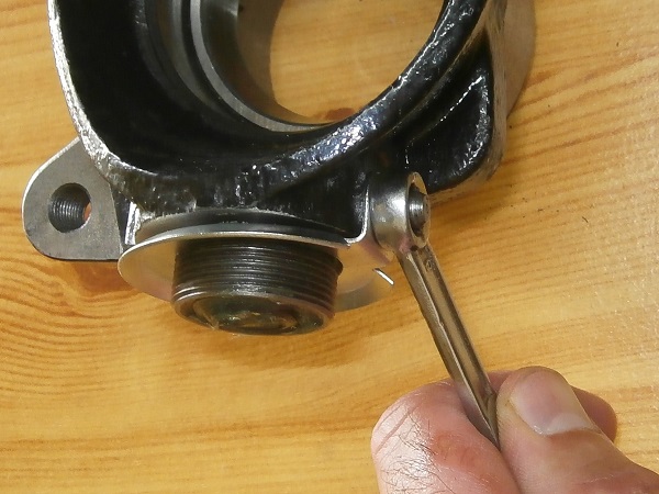
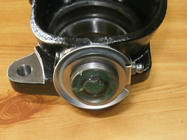
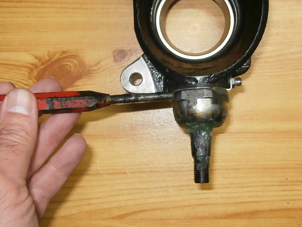
Op 14
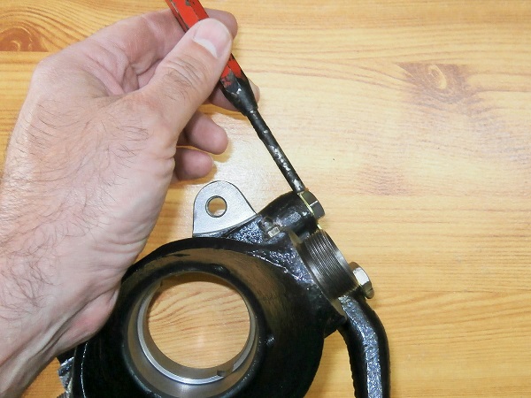
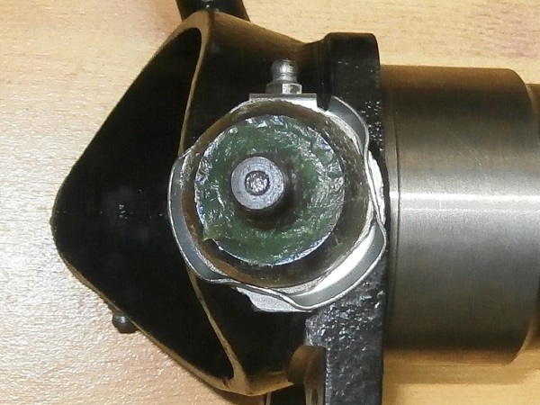
Straighten the locking washer. Use the flathead screwdriver.
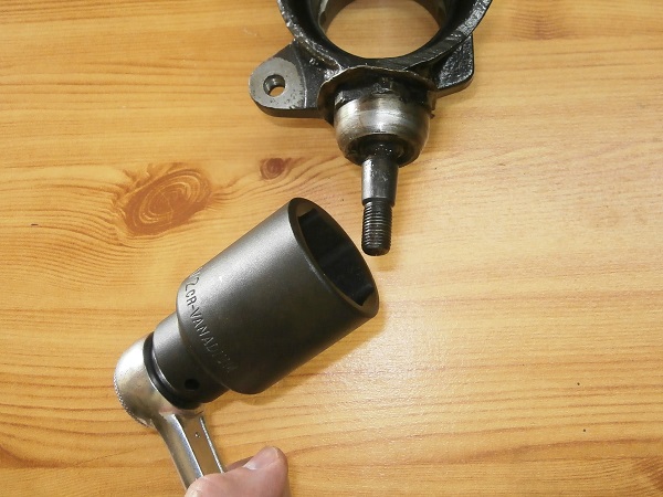
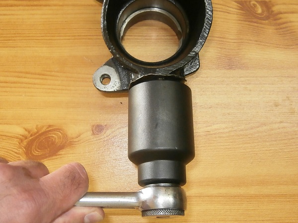
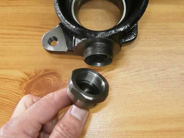
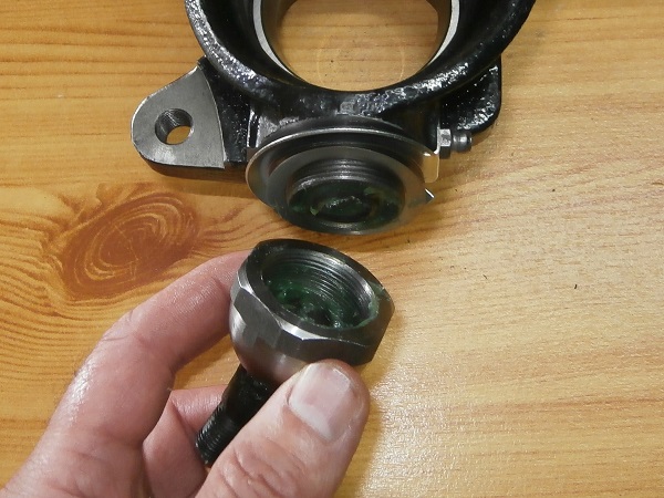
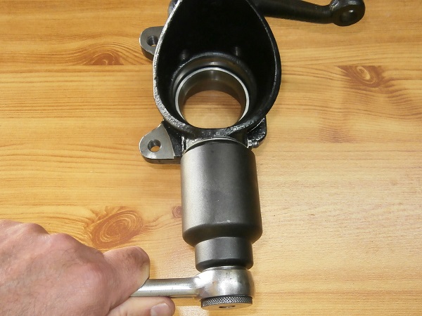
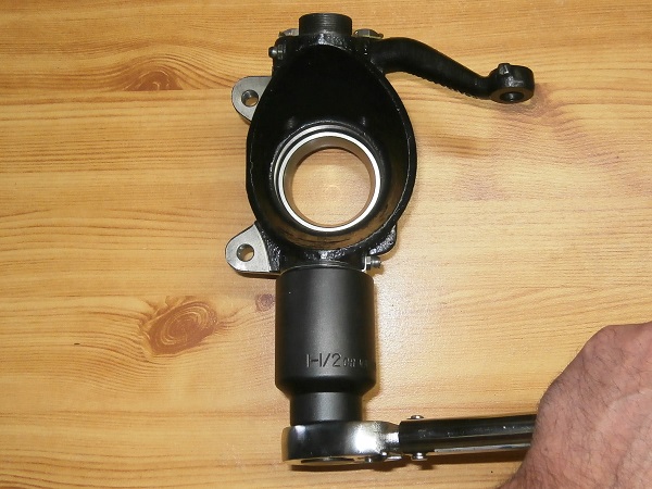
Op 15
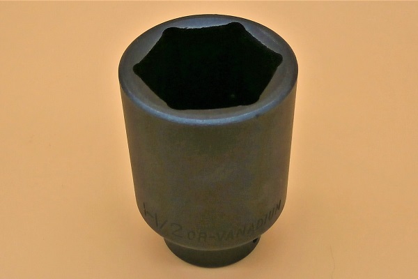
Remove the ball joint housing with its ball joint. Use the 38 mm deep socket (Tool 03).
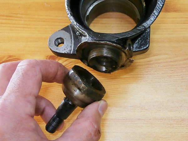
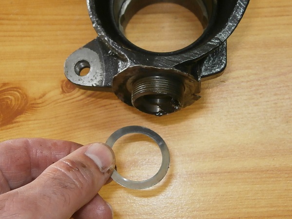
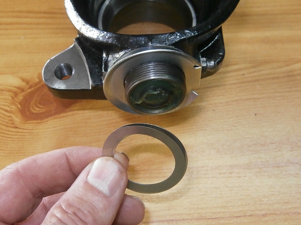
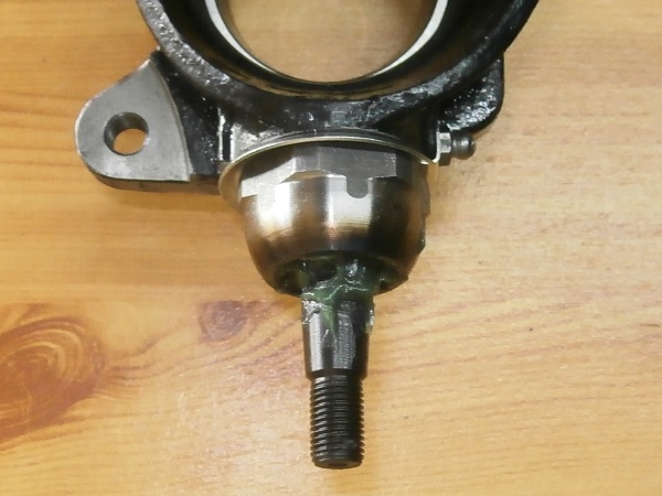
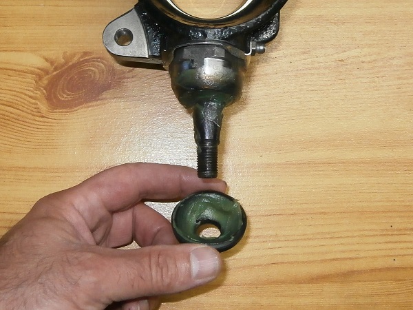
Op 16
Remove the seat, the spring, the shims and the locking washer.
Op 17
Remove the upper ball joint from the swivel hub. Proceed in the same way as the lower ball joint.

There is no spring at the upper ball joint.
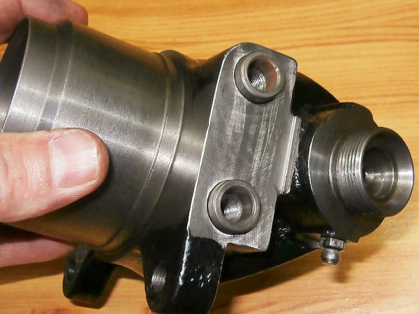
Remove the steering arm
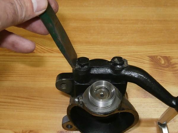
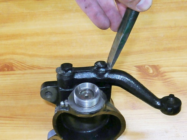
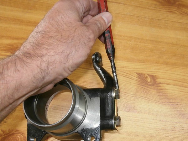
Op 18
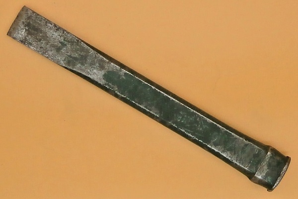
Flatten the steering arm lock. Use the chisel.
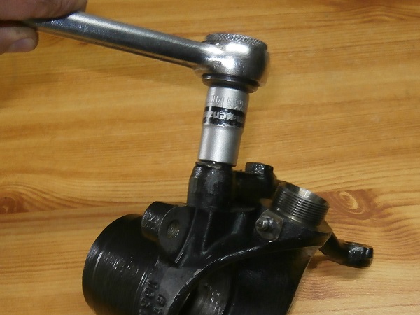
Op 19
Remove the 2 steering arm fixing bolts. Use the 14 mm socket.
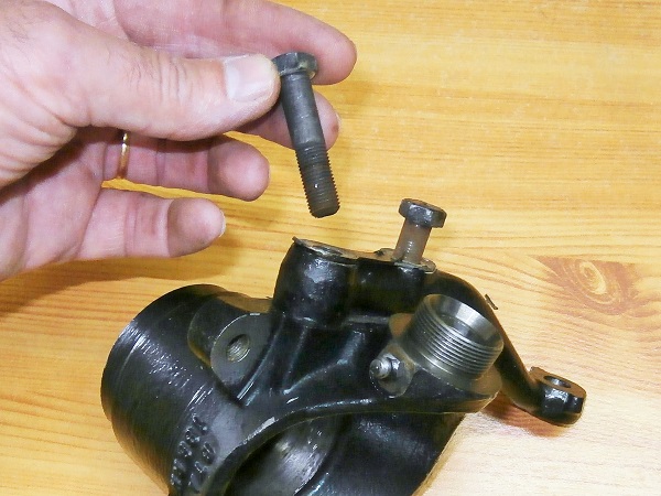
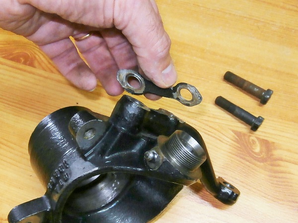
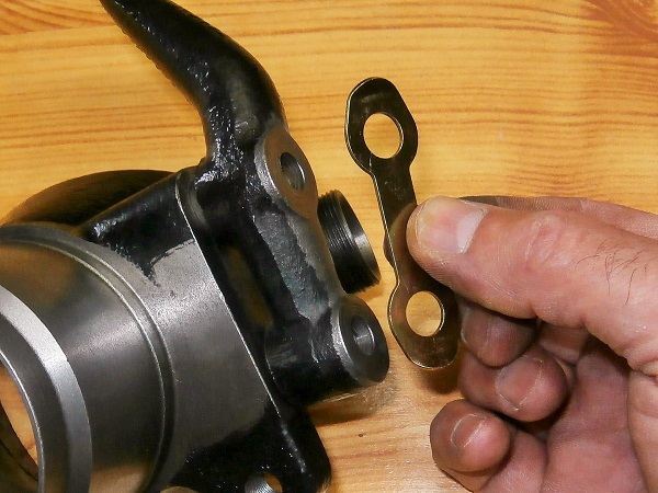
Op 20
Remove the steering arm lock.
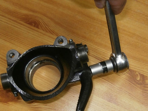
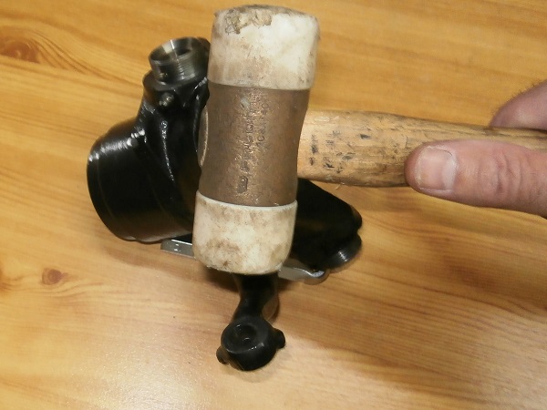
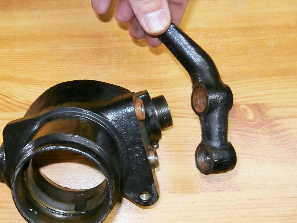
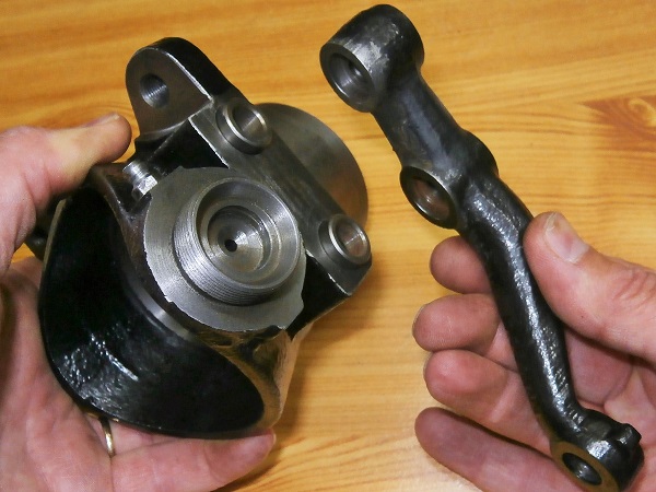
Op 21
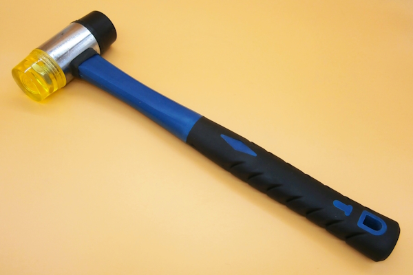
Remove the steering arm. Use the mallet.
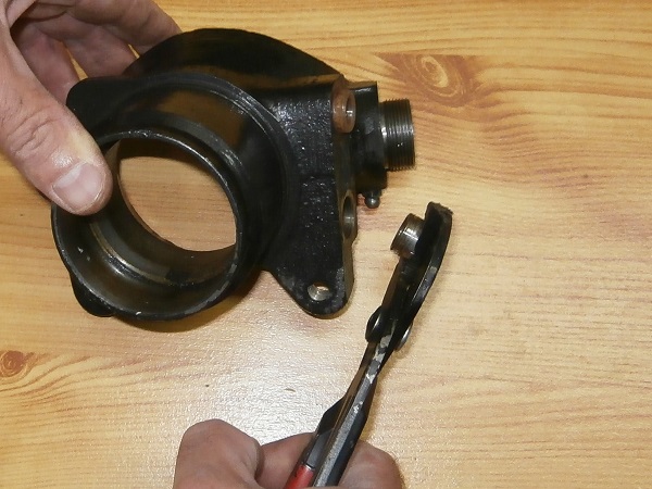
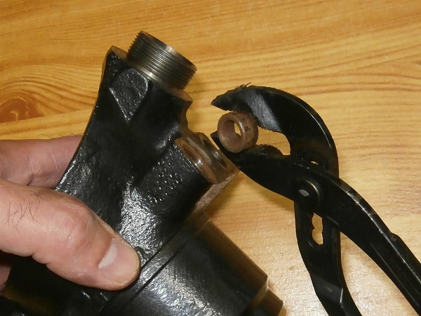
Op 22
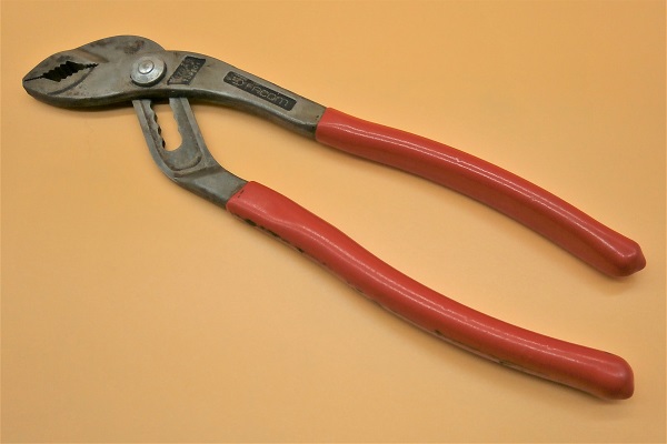
Remove the 2 steering arm spacers. Use the pliers.
Advertisement
Fit the steering arm
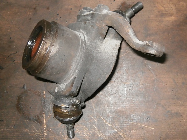
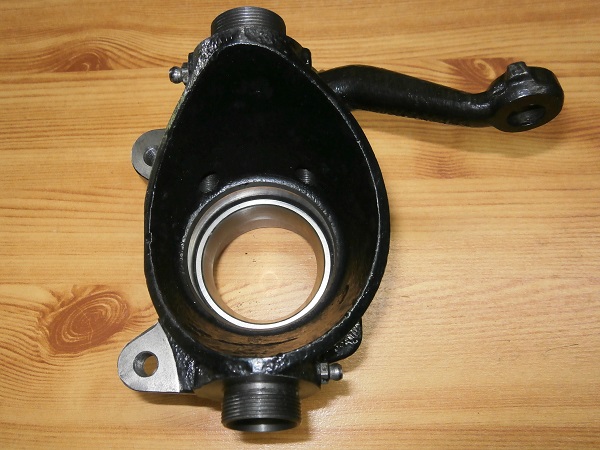
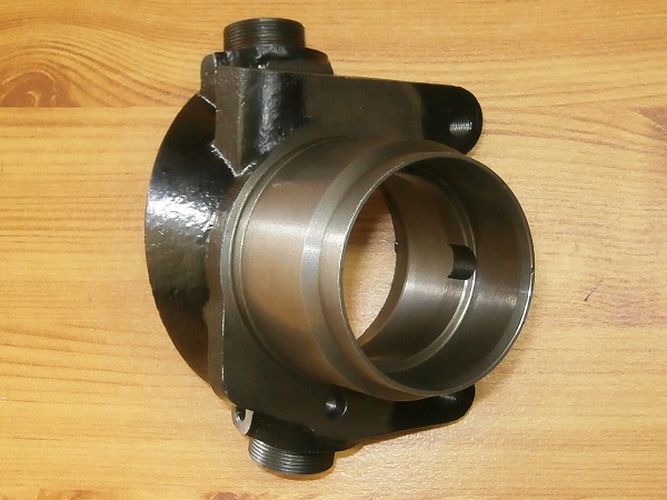
Op 23
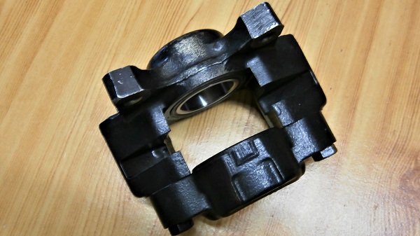
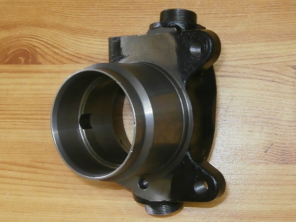
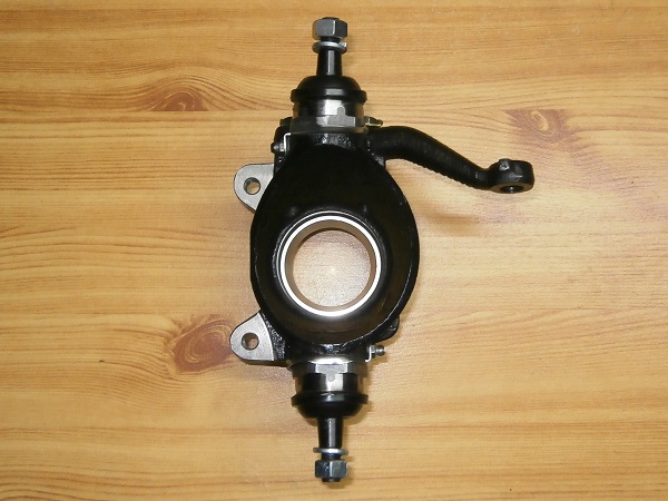
Take the new swivel hub (FAM2390).
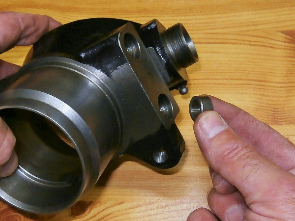
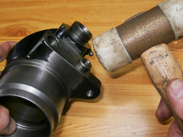
Op 24
Fit the 2 steering arm spacers. Use the mallet.
Op 25
Fit the steering arm.
Op 26
Fit the steering arm lock (2K5377).
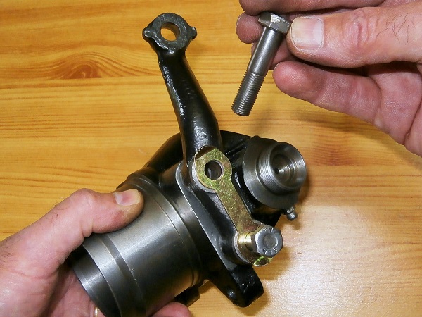
Op 27
Fit the 2 steering arm fixing bolts. Use the 14 mm socket.
Op 28
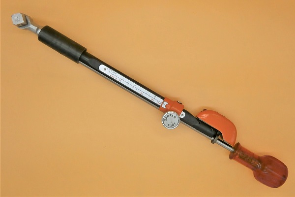
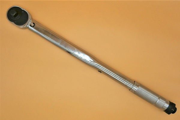
Tighten the 2 steering arm fixing bolts to a torque of 45 mN. Use the torque wrench.
Op 29
Fold the sides of the steering arm lock. Use the pin punch.
Fit the ball joints
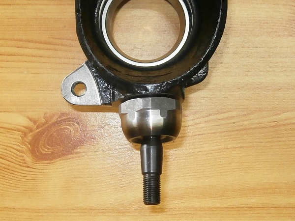
Op 30
Assemble the lower ball joint (kit GSJ166MS) without spring, without shim and without locking washer.
Tighten the ball joint housing by hand until there is no more play between the ball joint and its seat.
Do not lock the ball joint.
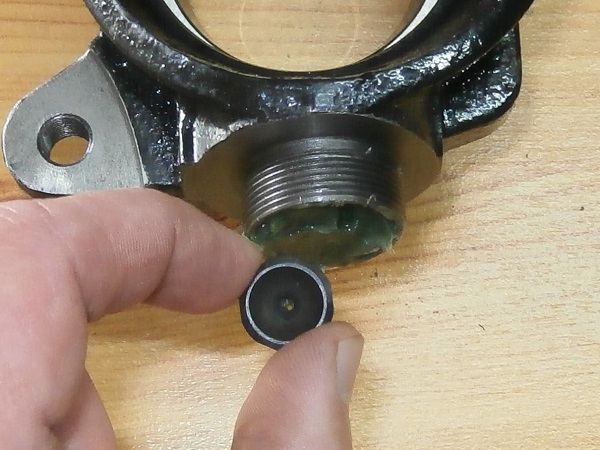
Do not forget to fit the ball joint seat.
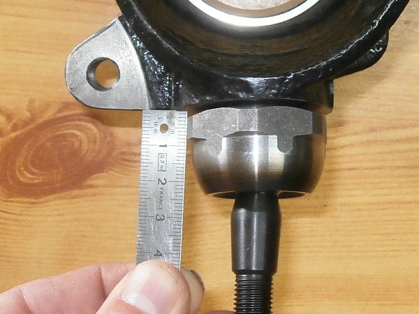
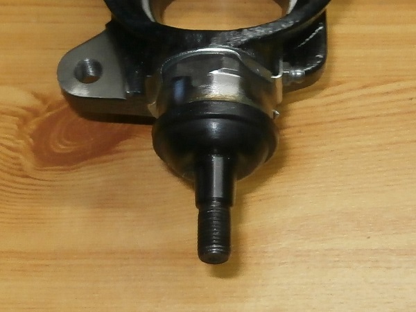
Op 31
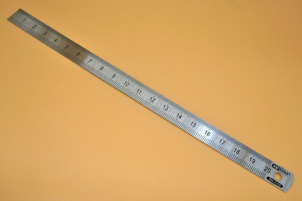
Measure the distance between the ball joint housing and the swivel hub. Use the ruler.
Subtract 0.90 mm to calculate the necessary shims.
Remove the ball joint.
Op 32
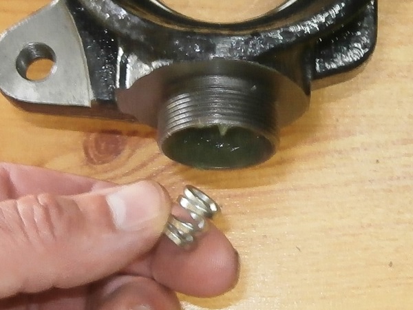
Pack with grease and position the spring and the seat (kit GSJ166MS).
Op 33
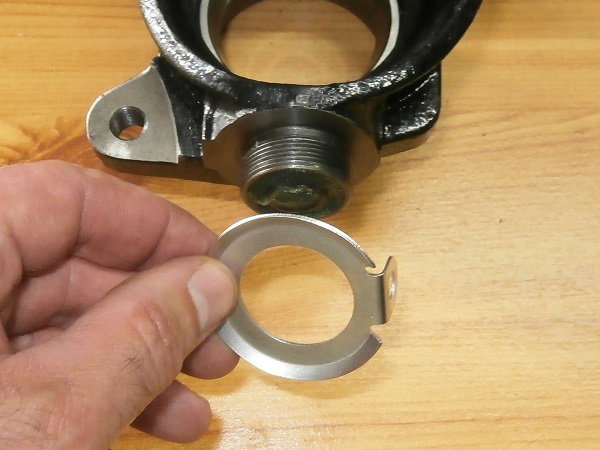
Fit the locking washer (kit GSJ166MS) and the grease nipple. Use the 8 mm spanner.
Op 34
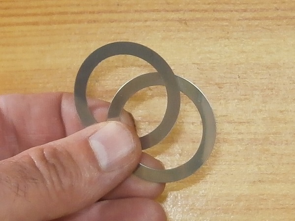
Fit the shims (kit GSJ166MS).
The thickness of the shims was defined during Op 31.
Op 35
Pack the ball joint with grease and assemble it on the swivel hub. Use the 38 mm deep socket.
Op 36
Tighten the ball joint housing to a torque of 102 mN. Use the torque wrench.
Op 37
Check that the ball joint can move freely in all planes after tightening.
Op 38
Fold the locking washer against 3 flats of the ball joint housing. Use the pin punch.
Op 39
Fit the dust cover (kit GSJ166MS). Push by hand.
Op 40
Fit the upper ball joint (kit GSJ166MS). Proceed in the same way as the lower ball joint.
There is no spring at the upper ball joint.
Advertisement
Fit the swivel hub
Op 41
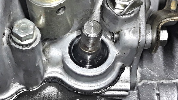
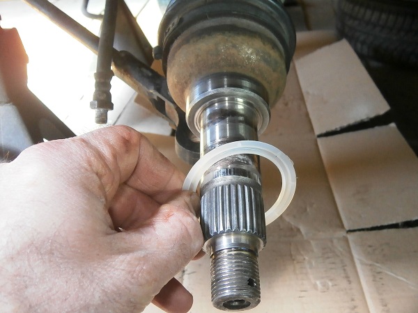
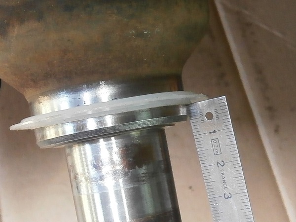
Fit the water shield on the CV joint shaft.
It must be 6 mm from the shoulder. Use a ruler.
Grease the outer face of the water shield.
Op 42
Fit the swivel hub on the CV joint shaft.
Fit the lower ball joint in the lower arm and the upper ball joint in the upper arm.
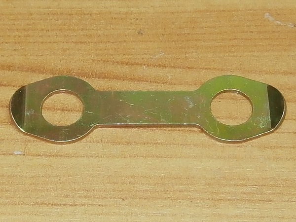
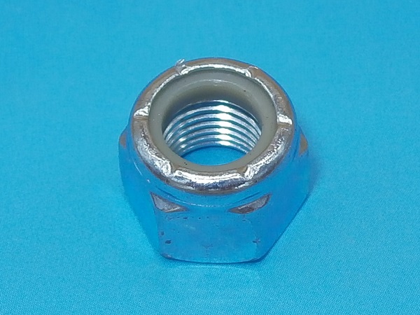
Fit the spring washers (GFK1127 included in GSJ166MS kit) and lightly screw the nuts (GFK3214 included in GSJ166MS kit) on the 2 ball joints.
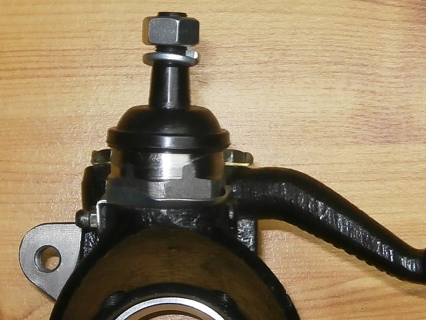
Op 43
Screw the nuts of the lower and upper ball joints. Use the 18 mm socket.


Op 44
Tighten the nuts of the lower and upper ball joints to a torque of 52 mN. Use the torque wrench.


Op 45
Fit the track rod end in the steering arm.


Op 46
Fit the brake disc shield.
Fit the rear fixing tab on the track rod end.
Op 47
Screw the track rod end nut (GFK3323). Use the 9/16'' socket.
Tighten this nut to a torque of 30 mN. Use the torque wrench.


Op 48
Fit the drive flange, the brake disc and the caliper (➔ see the tutorial ''Front brake discs change'' Op 12 to 18).
Op 49
Fit the brake pads and the wheel (➔ see the tutorial ''Front brake pads change'' Op 10 to 16).
The End