
This tutorial is also available in French
➔

Ignition timing adjustment on Austin Mini
Vehicle ➔ Mini 1000 year 1991 automatic gearbox
Difficulty ➔ Medium

Time ➔ 3 hours
Summary
Advertisement
Advertisement

Recommendations

In the past, the distributor was commonly called delco (and the distributor cap delco cap). Simply because Delco was one of the main manufacturers of distributors.
The contact breaker points were also called platinum-plated screws.

Adjusting the contact breaker points requires turning the crankshaft with great precision. On a Mini with an automatic gearbox, the method of turning one of the front wheels does not work. The correct method is to remove the small rubber grommet located above the torque converter housing to allow access to the starter motor ring gear. Then simply lever the ring gear teeth with a flathead screwdriver and turn the crankshaft. It's tedious but it works.
When performing various operations, always turn the crankshaft in the direction of engine rotation. This allows for play to be taken up.
To ensure good ignition of the air/petrol mixture, the spark plug must fire slightly before the piston reaches its top dead center. Thus, the air/petrol mixture can burn before the piston starts its descent. This is called ignition timing. On our 1991 Mini, the ignition timing must be set to 8°.
There is a second rubber grommet (larger than the previous one) on the torque converter housing of a Mini with an automatic gearbox. This cap allows access to the torque converter graduations. These graduations allow positioning piston #1 a few degrees before top dead center with great precision.
In this tutorial, we have detailed 2 methods for adjusting the ignition timing :
• The static adjustment (test light) : method adapted to a first adjustment following, for example, the removal of the distributor or for people who do not have a timing light.
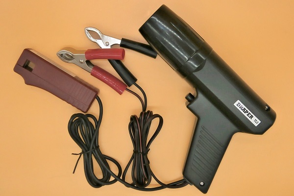
• The dynamic adjustment (timing light) : the simplest and most precise method.
• The static adjustment (test light) : method adapted to a first adjustment following, for example, the removal of the distributor or for people who do not have a timing light.
• The dynamic adjustment (timing light) : the simplest and most precise method.
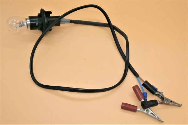
A test light is simply a 12V bulb mounted on a socket powered by 2 electrical wires. Crocodile clips attached to the end of these wires facilitate connection.
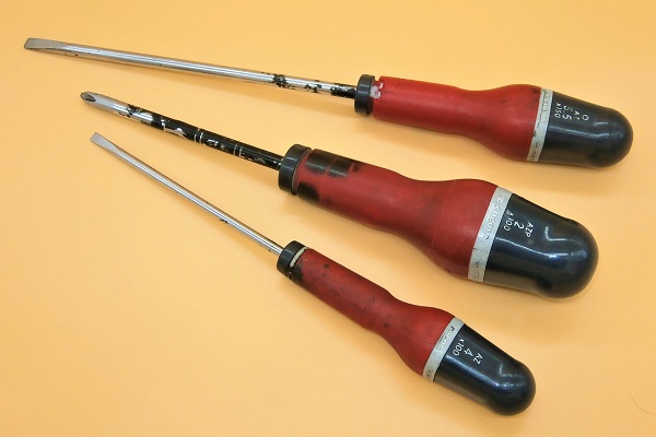
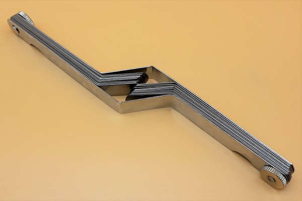
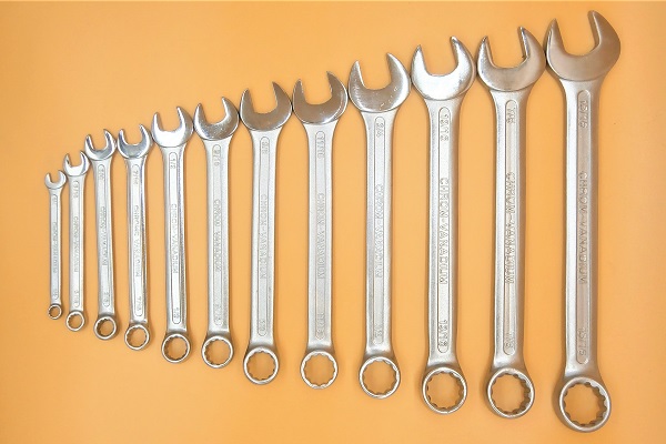
Required Tools
Sponsored links by

Warning light
Advertisement
Remove the distributor cap
Op 01
Remove the grille (➔ see the tutorial ''Grille removal'' Op 01 to 04).
Op 02
Locate where the distributor is.
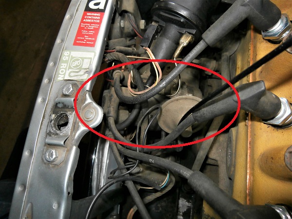
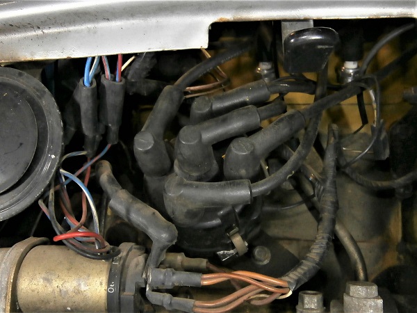
Op 03
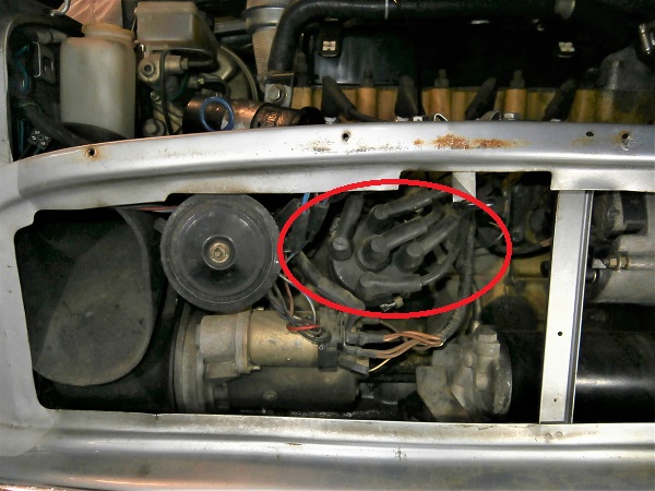
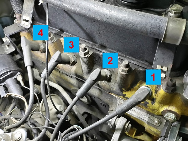
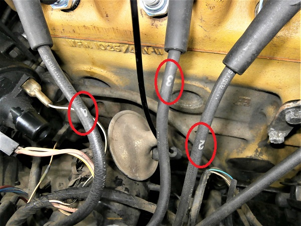
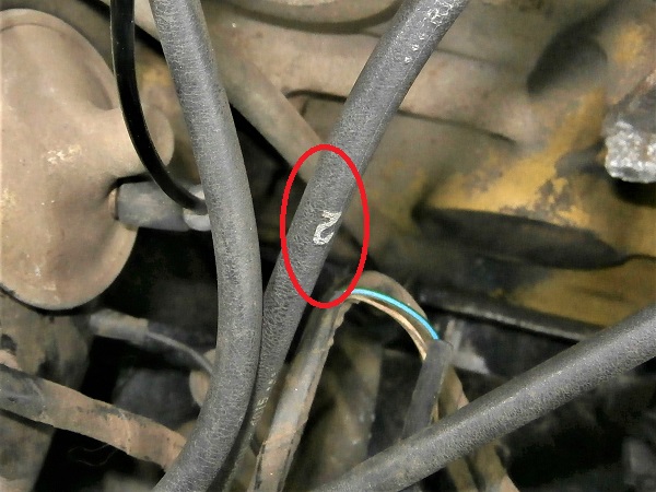
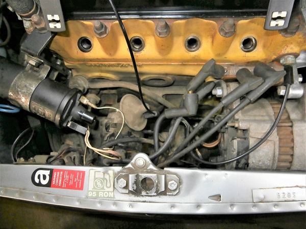
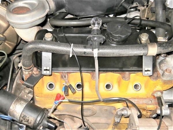
Verify that the spark plugs ignition wires are well identified.
Otherwise, write the corresponding spark plug number on each of the 4 cables.
The spark plugs are generally numbered from 1 to 4 starting from the spark plug closest to the radiator (1st photo).
The identification of the ignition wires will make things easier during reassembly.
Op 04
Remove the 4 spark plugs (➔ see the tutorial ''Spark plugs change'' Op 01 to 02).
Leave the ignition wires connected to the distributor cap.
Op 05
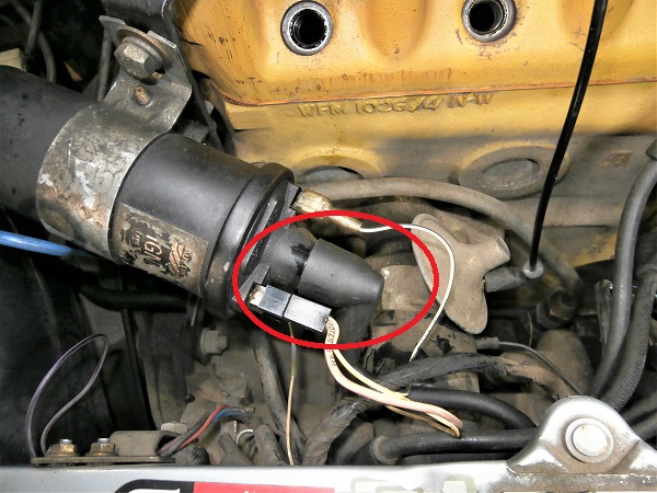
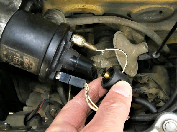
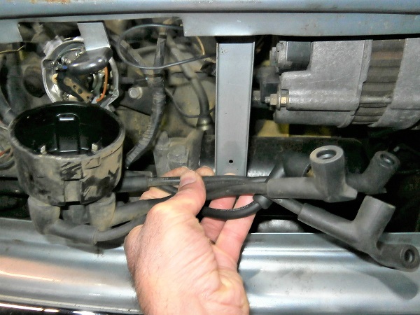
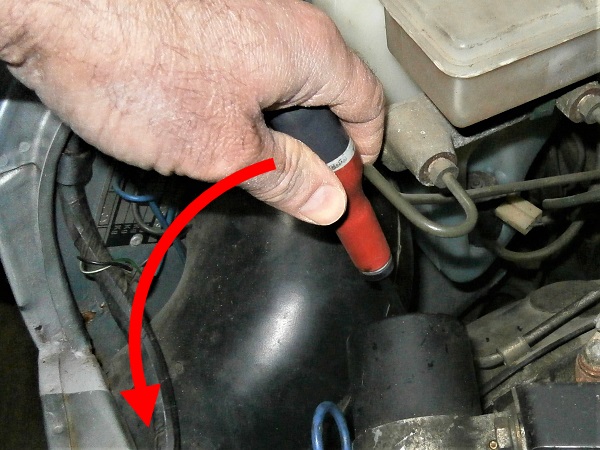
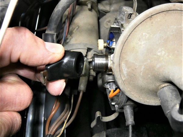
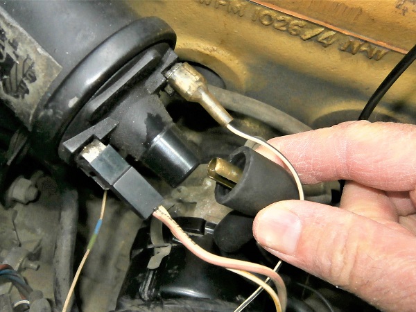
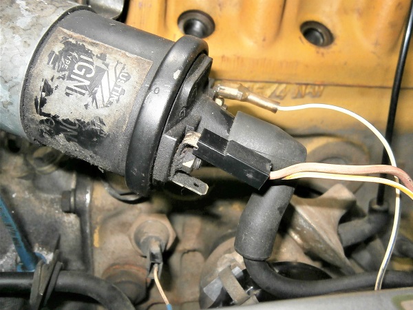
Disconnect the ignition wire from the ignition coil. Pull by hand.
Op 06
Remove the 2 fixing clips of the distributor cap. Pull by hand or use a flathead screwdriver.
Op 07
Remove the distributor cap (with the 5 ignition wires). Pull by hand.
Adjust the maximum opening of the contact breaker points
Op 08
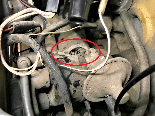
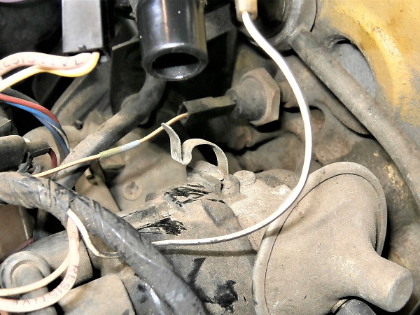
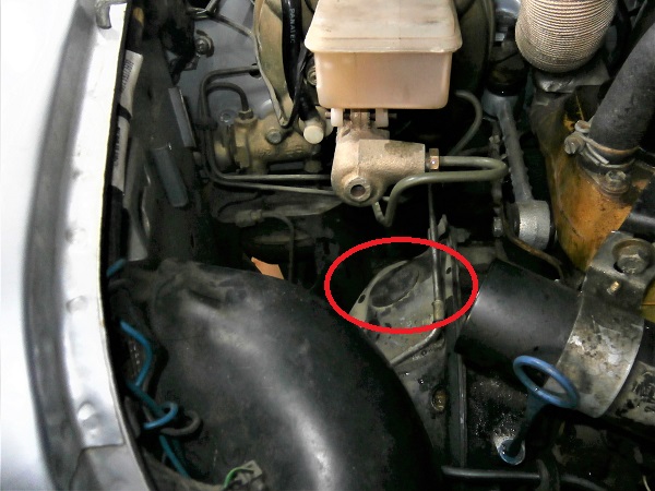
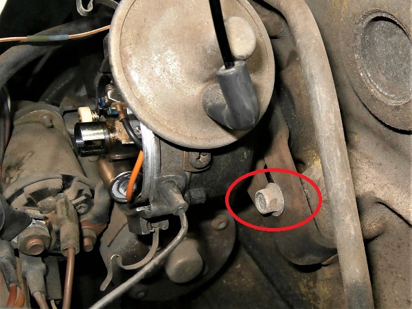
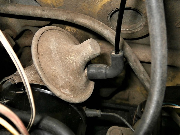
Locate where the small rubber grommet of the torque converter housing is.
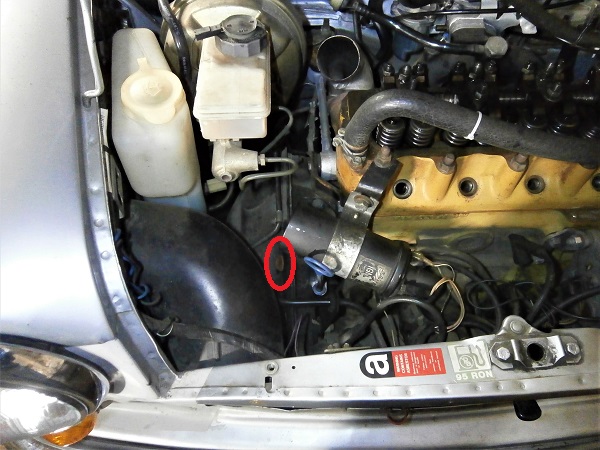
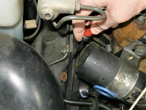
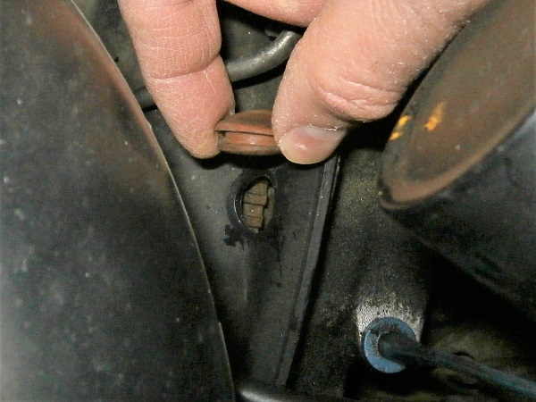
Op 09
Remove the small rubber grommet from the torque converter housing. Use the small flathead screwdriver.
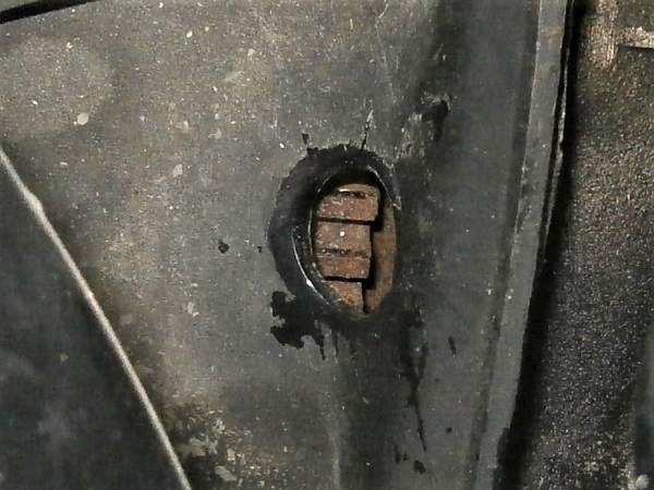
We see the teeth of the starter motor ring gear appearing. This is what will allow us to turn the crankshaft.
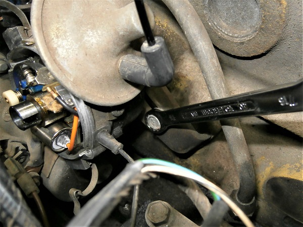
Op 10
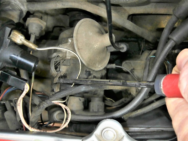
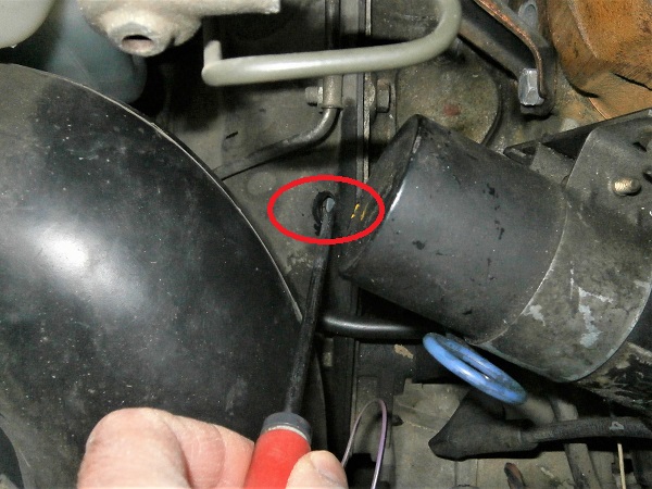
Introduce the large flathead screwdriver into the hole of the torque converter housing.
Verify that the crankshaft turns when levering on the teeth of the starter motor ring gear.
Op 11
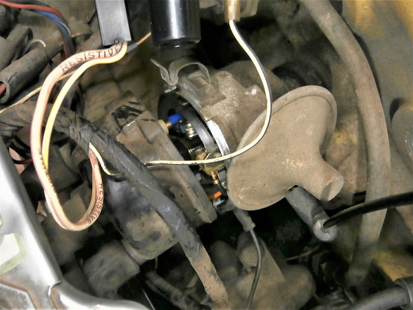
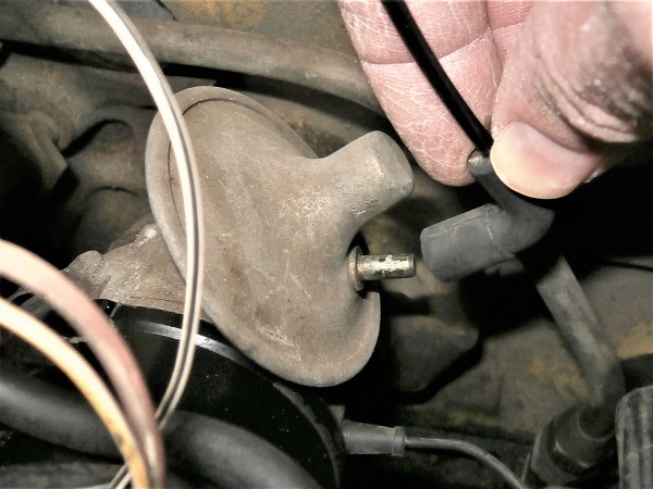
Remove the rotor arm. Pull by hand.
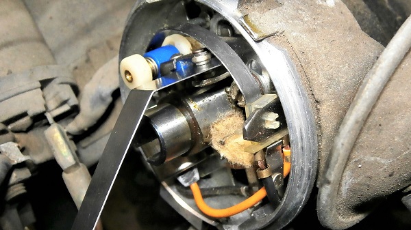
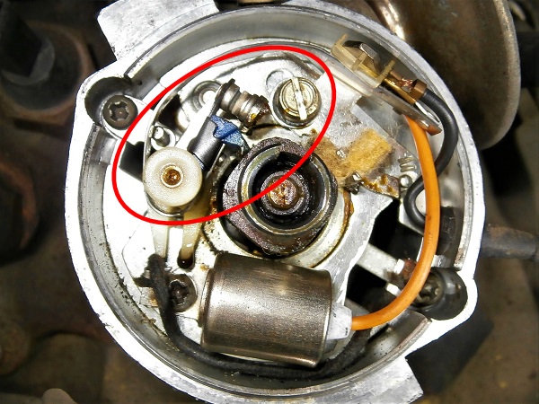
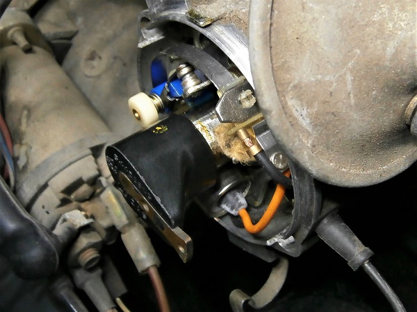
Op 12
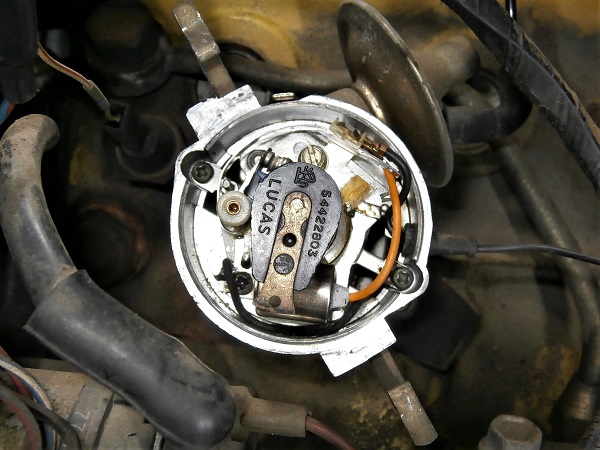
Locate where the contact breaker points are.
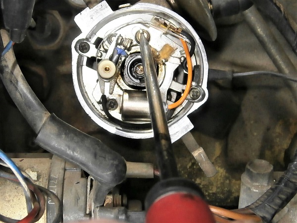
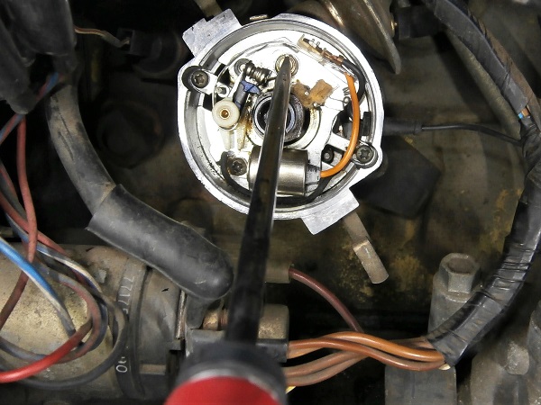
Op 13
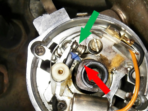
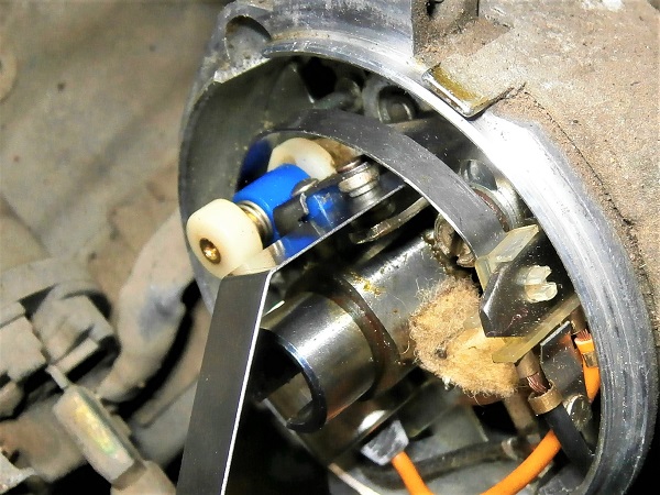
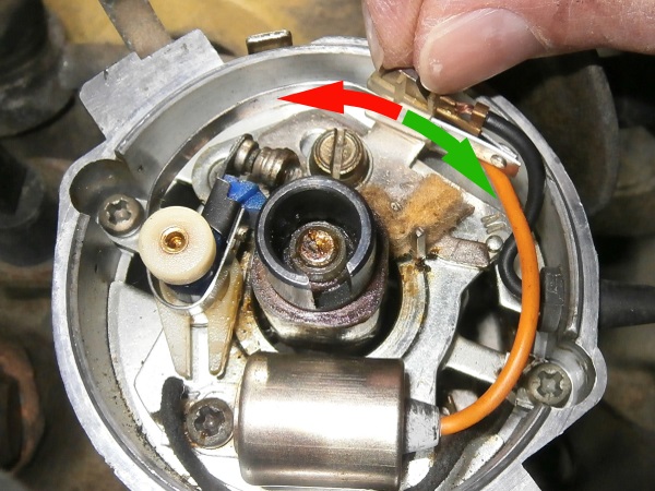
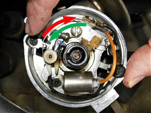
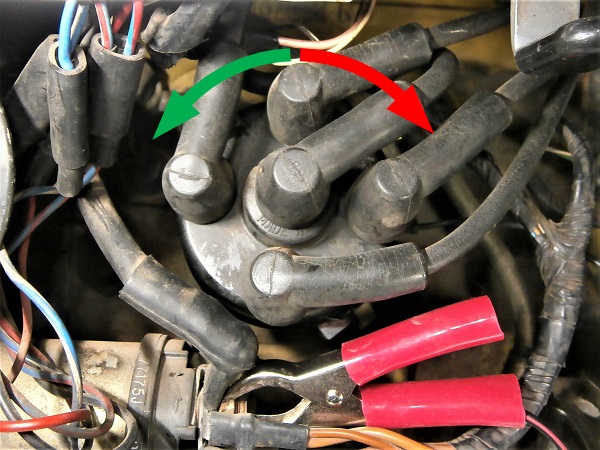
Turn the crankshaft to position the contact breaker points open to the maximum. Use the flathead screwdriver.
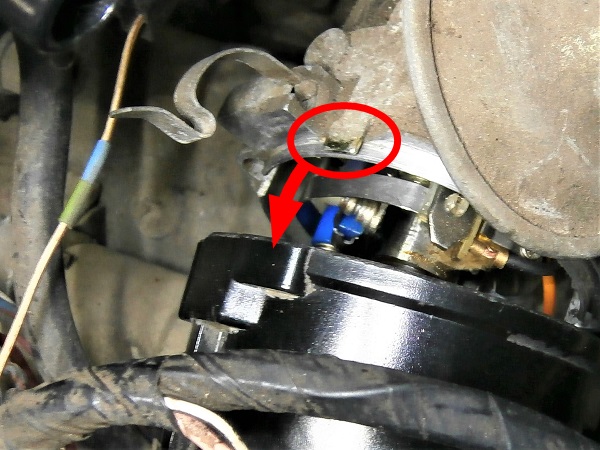
We can see on the 2nd photo :
• The cam is positioned at its maximum extension (red arrow).
• The contact breaker points are well separated (green arrow).
• The cam is positioned at its maximum extension (red arrow).
• The contact breaker points are well separated (green arrow).
Op 14
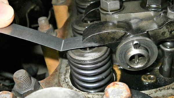
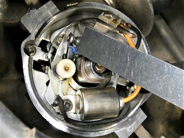
Verify that the gap of the contact breaker points is between 0.35 and 0.40 mm. Use the feeler gauges of 0.35 mm and 0.40 mm.
If the 0.35 gauge goes in and if the 0.40 gauge does not go in : the contact breaker points are well adjusted
(➔ go to Op 18).
If the 0.35 gauge does not go in or if the 0.40 gauge goes in : it will be necessary to adjust the contact breaker points. Go to the next Op.
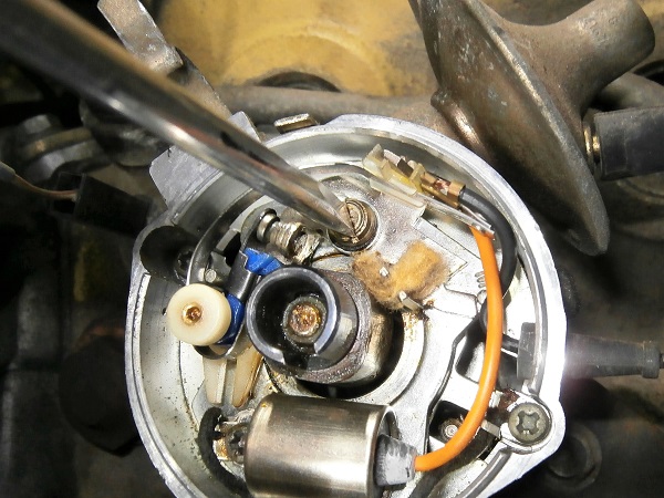
Op 15
Loosen very slightly the fixing screw of the contact breaker points support plate. Use the flathead screwdriver.
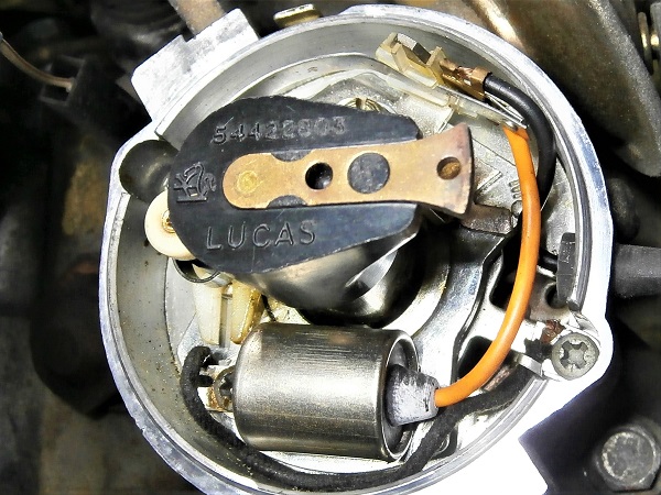
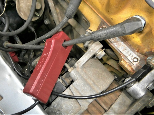
Op 16
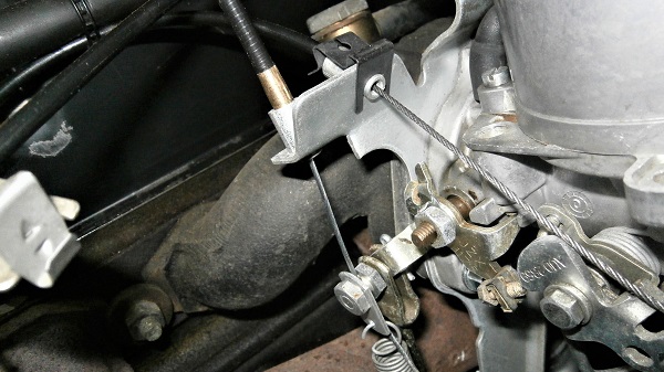
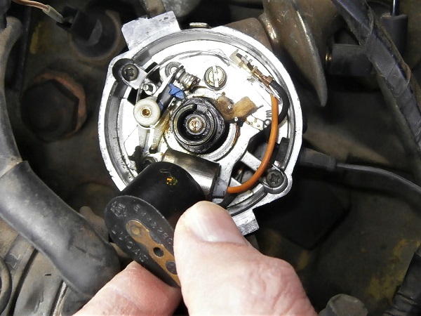
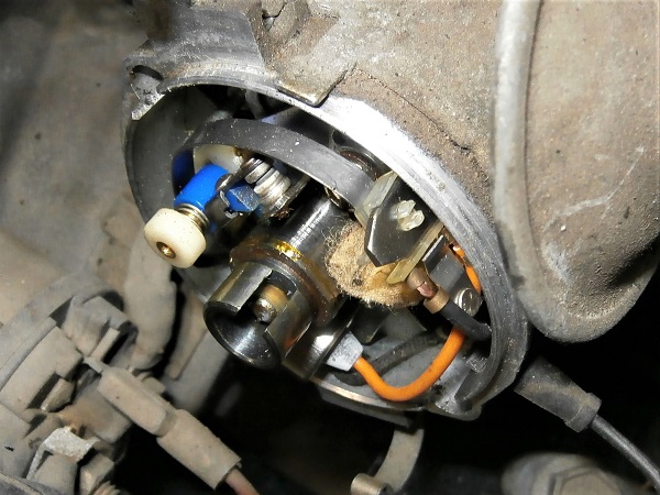
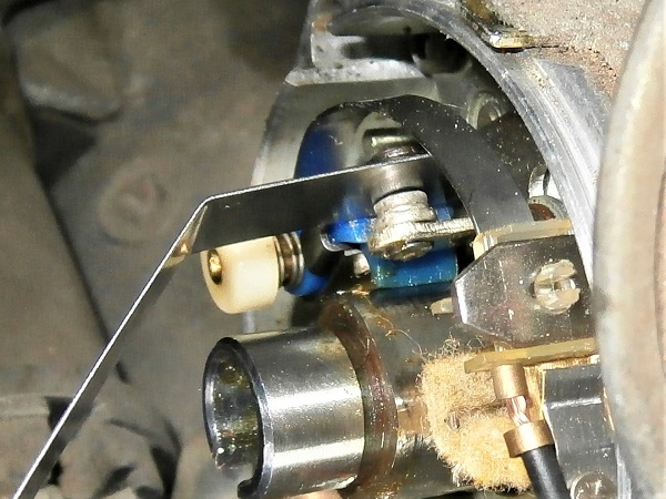
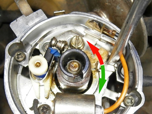
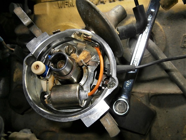
Correct the angular position of the contact breaker points support plate to obtain the correct breaker points gap (between 0.35 and 0.40 mm) :
•
Either push with your fingers (1st photo).
•
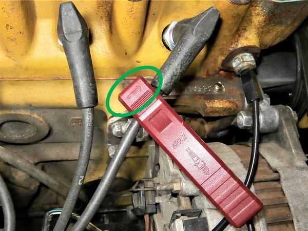
Or lever with a screwdriver between the V-shape and the small protuberance (2nd photo).
•
To increase the contact breaker points gap : rotate the plate clockwise (green arrow)
• To decrease the contact breaker points gap : rotate the plate counterclockwise (red arrow).
• To decrease the contact breaker points gap : rotate the plate counterclockwise (red arrow).
Op 17
Tighten the fixing screw of the contact breaker points support plate. Use the flathead screwdriver.
Once the screw is tightened, do not hesitate to make a final check of the contact breaker points gap. The plate may have moved slightly when tightening the screw. You never know.
Advertisement
Adjust the ignition timing statically (test light)
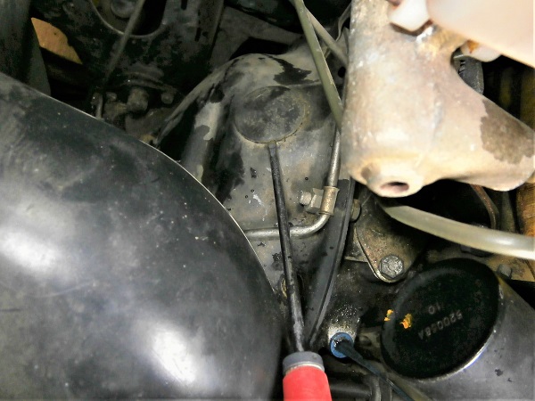
Op 18
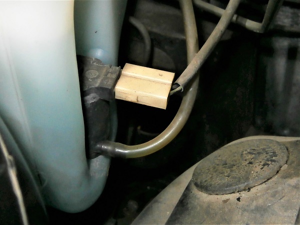
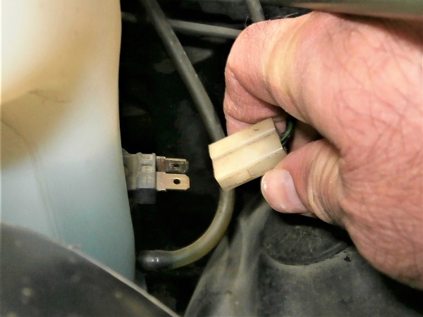
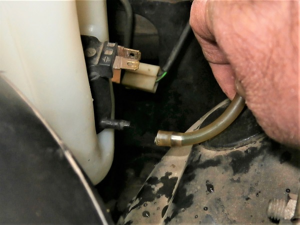
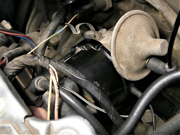
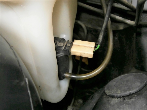
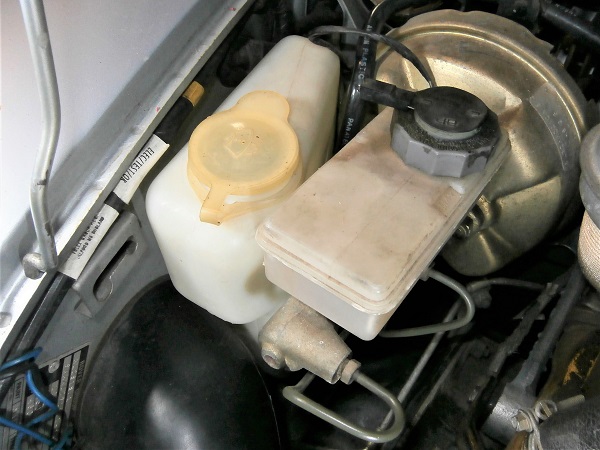
Disconnect the connector and the hose of the windscreen washer pump. Pull by hand.
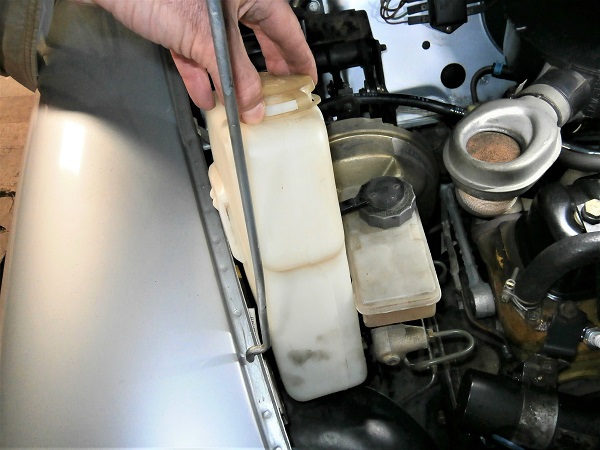
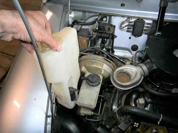
Remove the windscreen washer bottle. Pull by hand upwards.
Removing the windscreen washer bottle will make it easier for us to access the torque converter housing.
Place a drain pan under the Mini vertically to the windscreen washer bottle because the liquid will flow when the hose is disconnected.
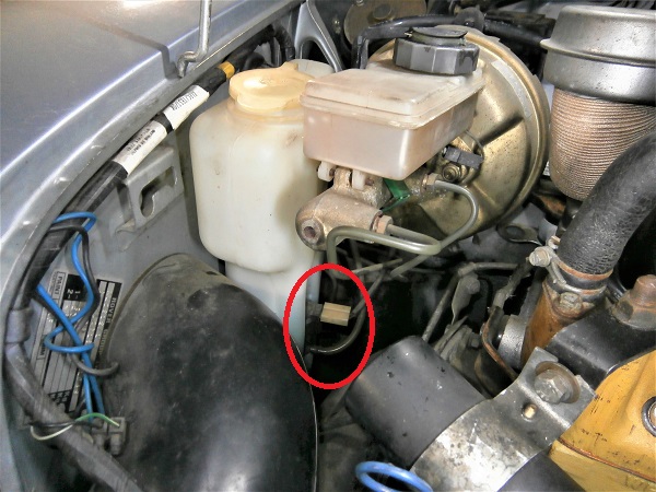
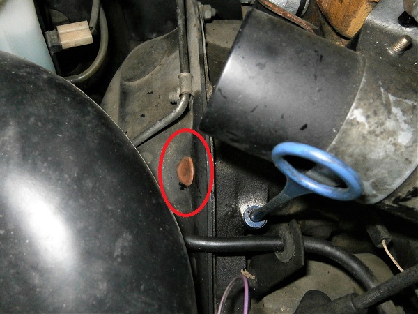
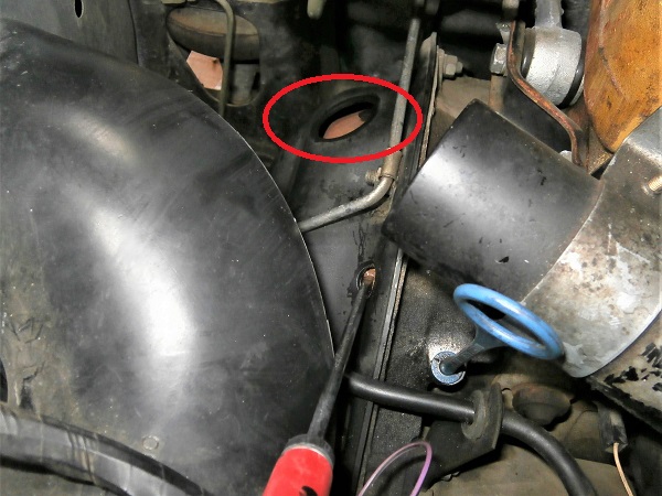
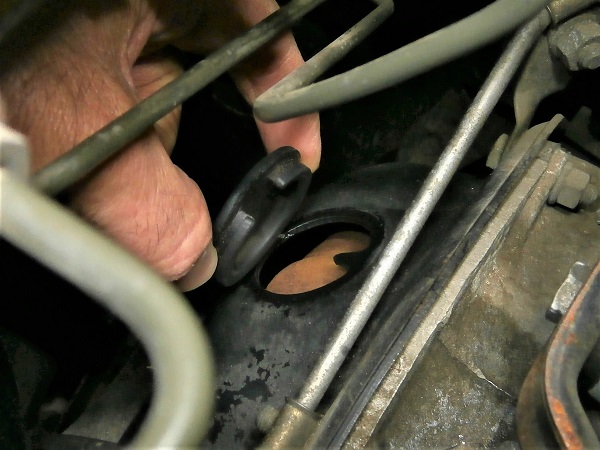
Op 19
Locate where the 2nd rubber grommet of the torque converter housing is (the largest).
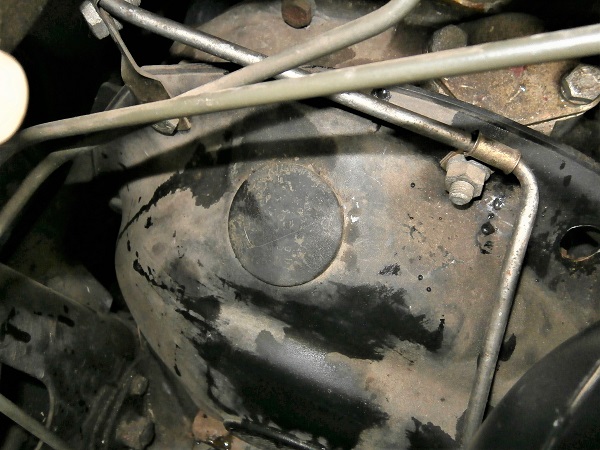
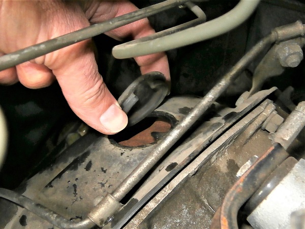
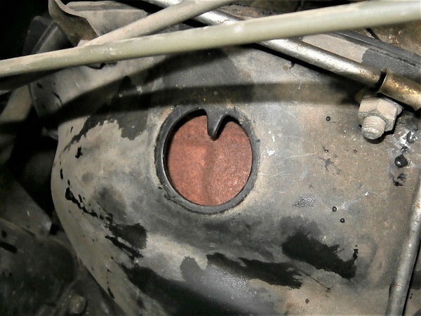
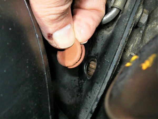
Op 20
Remove this 2nd rubber grommet. Use the flathead screwdriver.
We can finally see the torque converter.
It is through this hole that we will look for the appearance of the torque converter graduations.
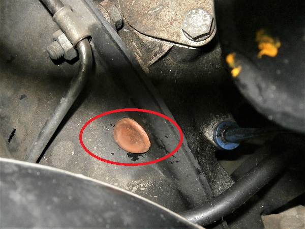
Op 21
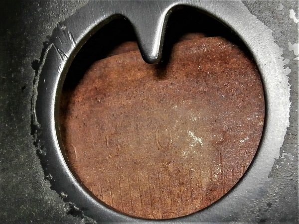
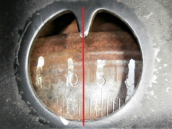
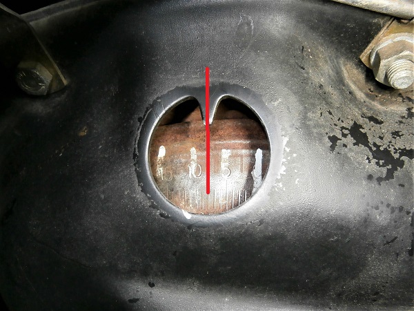
Turn the crankshaft to look for the torque converter graduations. Use the flathead screwdriver.
On our Mini classics, the torque converter is frequently oxidized. Consequently, it is particularly difficult to see the graduations. In addition, as the rotation of the crankshaft is really tedious, it is necessary to redouble your patience to successfully search for the graduations.
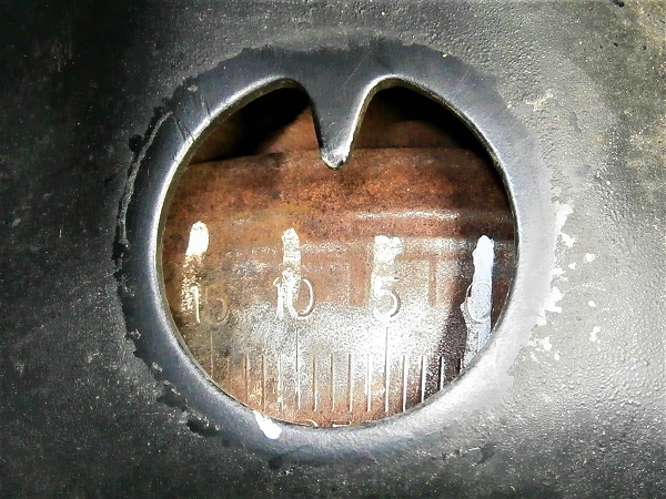
The 0 graduation appears when piston #1 is at its top dead center. I must admit that after several unsuccessful crankshaft turns, to facilitate my search, I watched for the arrival of piston #1 through the spark plug hole. Graduations miraculously appeared at that moment.
I was so happy to find the graduations that I immediately highlighted them with a marker (3rd photo).
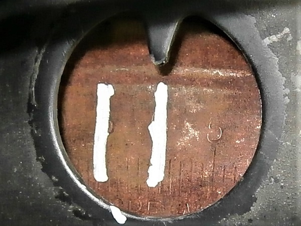
Op 22
Turn the crankshaft to position the 8° graduation in front of the torque converter housing mark. Use the flathead screwdriver.
These 8° correspond to the ignition timing that we must adjust.
Op 23
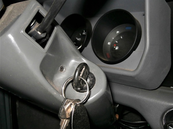
Turn on the ignition.
Do not operate the starter motor.
Op 24
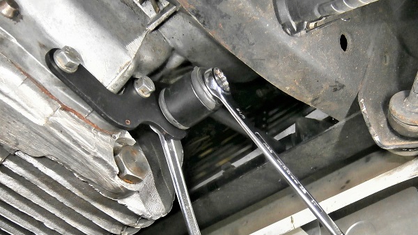
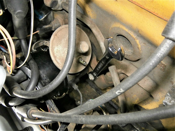
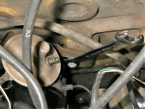
Loosen slightly the distributor clamp bolt. Use the 7/16'' spanner.
Op 25
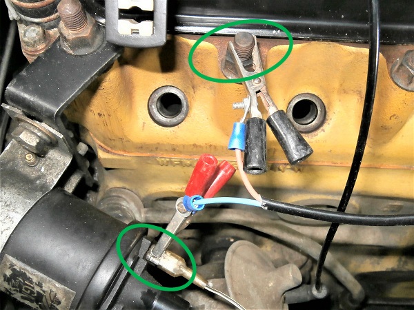
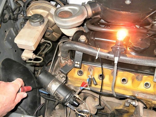
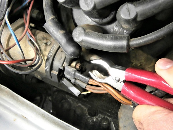
Connect the test light between the low voltage circuit and the ground.
Op 26
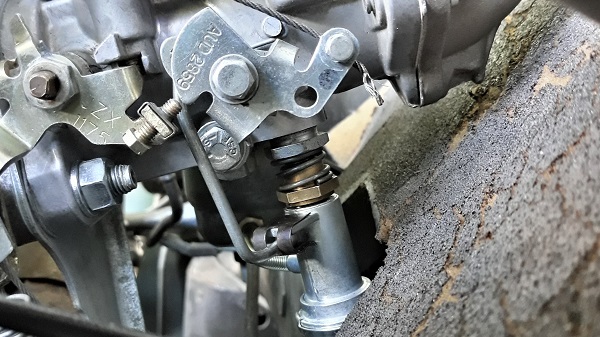
Rotate the distributor counterclockwise until the contact breaker points are closed (green arrow).
Rotate the distributor slowly clockwise to the exact position where the test light comes on (red arrow).
The light comes on when the contact breaker points open.

Op 27
Tighten the distributor clamp bolt. Use the 7/16'' spanner.
Op 28
As a safety measure, turn the crankshaft a full turn until the exact moment the test light comes back on.
Check that the 8° graduation is again positioned in front of the torque converter housing mark.
If the torque converter is misaligned, repeat the adjustment at Op 22.
Op 29
Turn off the ignition.
Fit the distributor cap
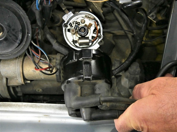
Op 30
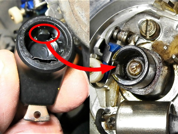
Fit the rotor arm on its axis.
To ensure the correct angular position, engage the boss of the rotor in the notch of the axis (1st photo).
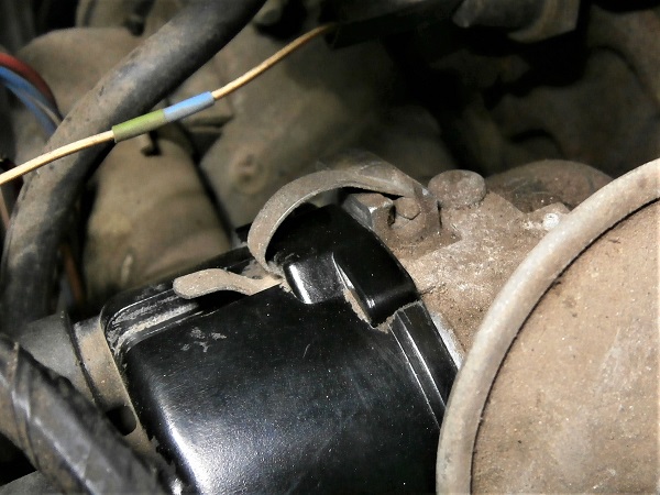
Op 31
Fit the distributor cap.
To ensure the correct angular position, engage the notch of the cap on the boss of the distributor (2nd photo).
Op 32
Fit the 2 distributor cap fixing clips. Push by hand.
Op 33
Connect the ignition wire to the ignition coil. Push by hand.
Op 34
Fit the 4 spark plugs and connect their ignition wires (➔ see the tutorial ''Spark plugs change'' Op 03 to 05).
This is when identifying the ignition wires becomes very useful.
Advertisement
Adjust the ignition timing dynamically (timing light)
Op 35
Start the Mini and let it reach its operating temperature.
Turn off the engine.
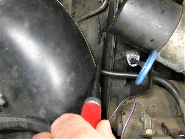
Op 36
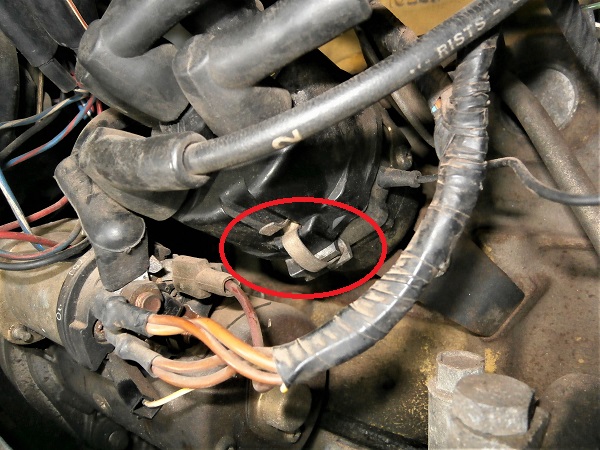
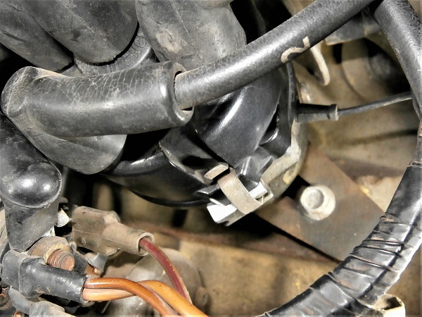
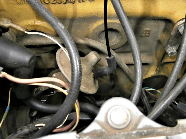
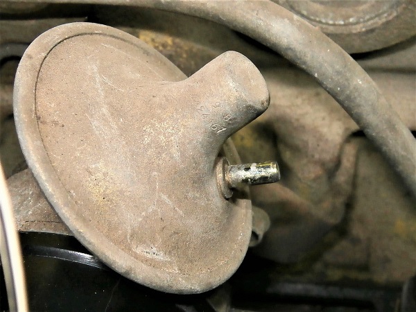
Disconnect the vacuum pipe from the distributor. Pull by hand.
The vacuum pipe must be disconnected so that the vacuum does not influence the distributor during the dynamic adjustment of the ignition timing.
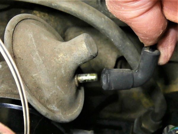
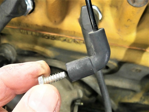
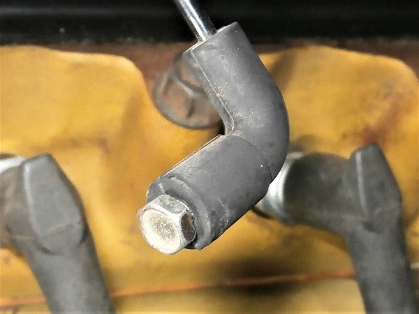
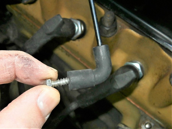
Op 37
Plug the vacuum pipe. Use a Ø4 mm screw.
It is preferable to plug the vacuum pipe to avoid any air intake that could disrupt the carburation.
Op 38
Loosen slightly the distributor clamp bolt. Use the 7/16'' spanner.
Op 39
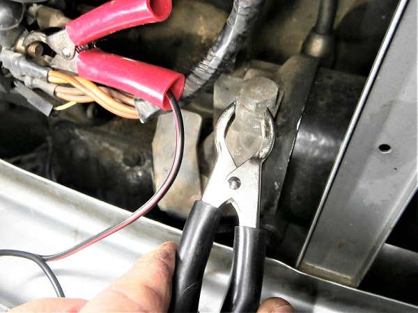
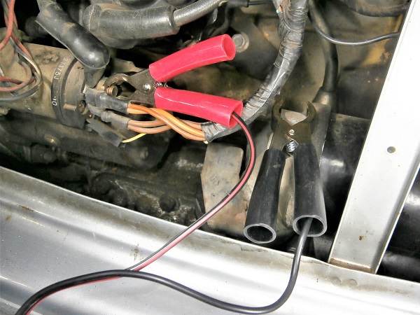
Connect the power supply of the timing light (12V).
As the battery is in the boot, the power cables of the timing light are not long enough to connect to it. It is therefore necessary to find a + and a ground in the engine compartment.
Op 40
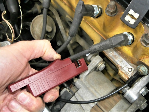
Fit the induction clamp on the ignition wire of spark plug #1.
Respect the mounting direction of the induction clamp. The arrow engraved on the clamp must be oriented towards the spark plug (3rd photo).
Op 41
Start the engine.
Pull the choke a little to obtain a slightly accelerated engine speed (≈ 1000 rpm).
Let the engine run.
The slightly accelerated engine speed will generate a higher frequency of flashes from the timing light and the vision of the graduations will be clearer.
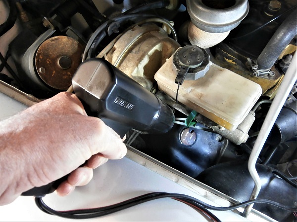
Op 42
Illuminate the torque converter with the timing light.
Verify that the 8° graduation appears in front of the torque converter housing mark.
The timing light produces a flash synchronized with the spark plug spark. This stroboscopic flash gives the impression that the torque converter is stationary. We then see the graduation corresponding to the ignition timing appearing.
If the 8° graduation appears : the ignition timing is well adjusted
(➔ go to Op 44).
If another graduation than 8° appears : it will be necessary to improve the adjustment of the ignition timing. Go to the next Op.
Op 43
Rotate the distributor very slightly to adjust the ignition timing to 8°.
Be careful, it's very sensitive !
•
To increase the ignition timing : rotate the distributor clockwise (red arrow)
• To decrease the ignition timing : rotate the distributor counterclockwise (green arrow).
• To decrease the ignition timing : rotate the distributor counterclockwise (green arrow).
Op 44
Turn off the ignition.
Op 45
Tighten the distributor clamp bolt. Use the 7/16'' spanner.
Once the nut is tightened, do not hesitate to make a final check with the timing light. Two precautions are better than one.
Op 46
Remove the screw from the vacuum pipe.
Connect the vacuum pipe to the distributor. Push by hand.
Op 47
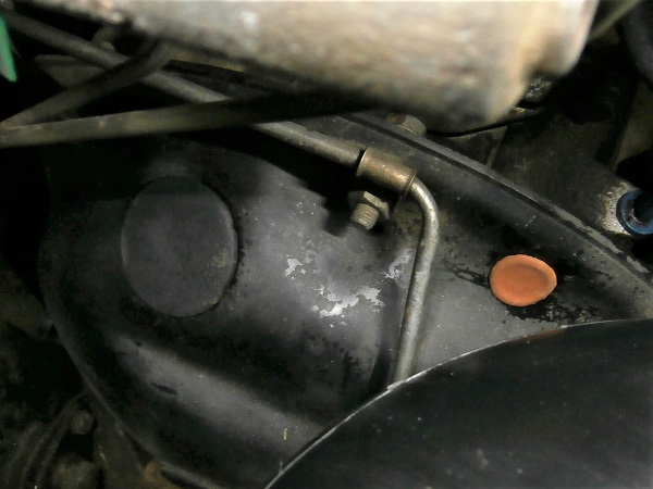
Fit the 2 rubber grommets of the torque converter housing.
Op 48
Fit the windscreen washer bottle.
Connect the windscreen washer hose and connector.
Op 49
Fit the grille (➔ see the tutorial ''Grille removal'' Op 05 to 06).
The End