
This tutorial is also available in French
➔

Rear brake shoes change on Austin Mini
Vehicle ➔ Mini 1000 year 1991 automatic gearbox
Difficulty ➔ Medium
Time ➔ 2 hours
Summary
Advertisement
Advertisement

Recommendations

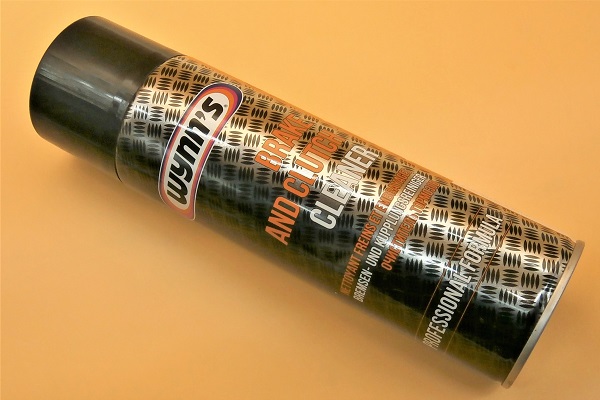
Never use compressed air when cleaning the brake system. You could inhale very harmful dust. Use brake cleaner and a cloth. Your lungs will thank you.
Always change brake shoes in pairs (RH wheel + LH wheel).
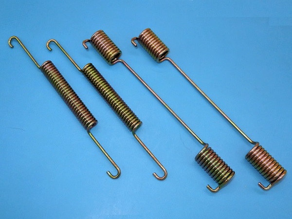
When changing brake shoes, always change the shoes return springs.

Never press the brake pedal when a drum is removed, as this would eject the pistons from the wheel cylinder.
When changing brake shoes, it is recommended to change or repair the wheel cylinders (GWC1102). Indeed, if the shoes are worn, it is very likely that the cylinder seals are also at the end of their life. If the cylinder seals give up the ghost, you will not only have to remove the drums again to change the cylinders, but also change the shoes again because they will have been soiled by the brake fluid.
The selling price of a new wheel cylinder is not much higher than the price of the seals kit for refurbishment. Analyze the cylinders carefully before placing your order. If in doubt (oxidation, scratches, defect) order new wheel cylinders.
We decided to invest in ''Genuine'' quality wheel cylinders because we had a bad surprise with an ''adaptable'' one. From the first bleed, the tapping of the adaptable wheel cylinder where the bleed nipple is fitted tore off.
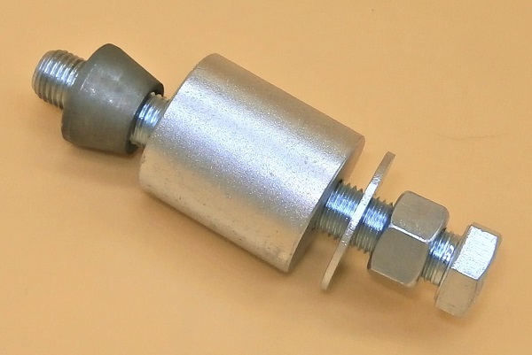
The wheel cylinder circlip tool (Tool14) greatly facilitates our task when reassembling the wheel cylinder on the backplate. For about ten pounds it is really a shame to do without it.
Bed in the new brake shoes. Do not brake suddenly during the first few kilometers. This allows the shoes to adjust with the drums.
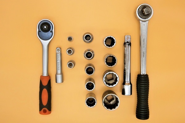
Required Tools
Sponsored links by


Spare Parts
Our Partners


Packaging :
•
GBK1834 : The kit includes 4 springs for the 2 rear brakes.
• GBS834AF : The set includes 4 shoes for the 2 rear brakes.
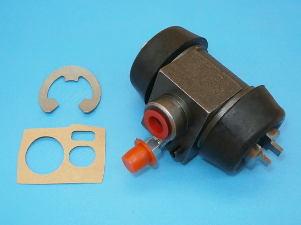
• GWC1102 : Wheel cylinders are sold individually. 2 wheel cylinders are required for a vehicle. The rear wheel cylinder is usually delivered with 1 bleed nipple (513118A), 1 circlip (17H7949) and 1 gasket (37H4642) but this is not always the case. Inquire before placing the order.
• The other parts above are sold individually.
• GBS834AF : The set includes 4 shoes for the 2 rear brakes.
• GWC1102 : Wheel cylinders are sold individually. 2 wheel cylinders are required for a vehicle. The rear wheel cylinder is usually delivered with 1 bleed nipple (513118A), 1 circlip (17H7949) and 1 gasket (37H4642) but this is not always the case. Inquire before placing the order.
• The other parts above are sold individually.
Advertisement
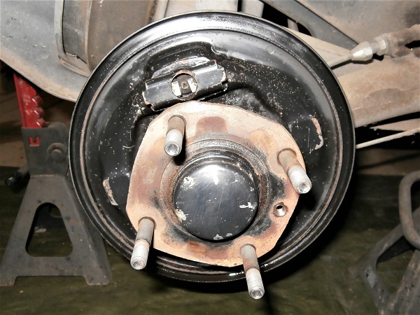
Remove the brake drum
Op 01
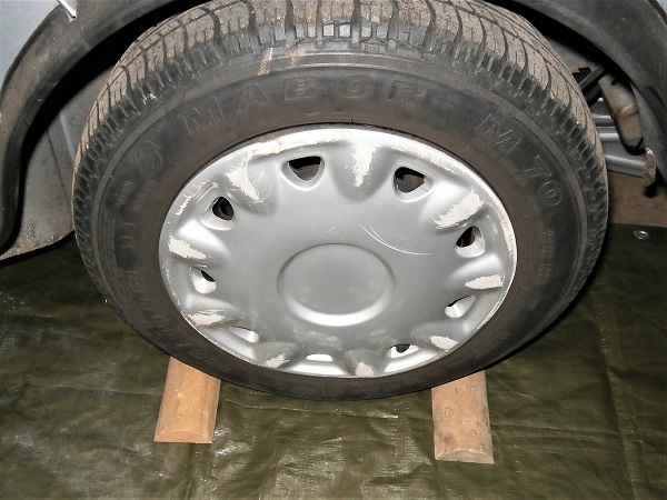
Immobilize the front wheels. Place wooden chocks.
We are going to remove one of the rear wheels while the handbrake is released. It is imperative to perfectly secure the Mini.
Op 02
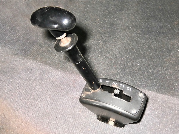
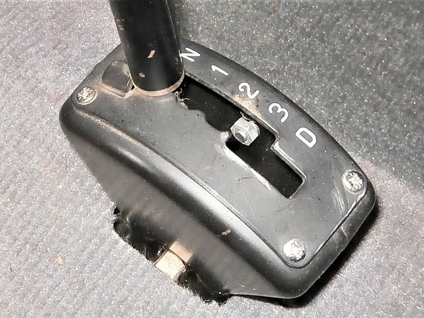
On an automatic Mini, place the selector in the ''N'' position.
On a Mini with manual gearbox, engage 1st gear.
Op 03
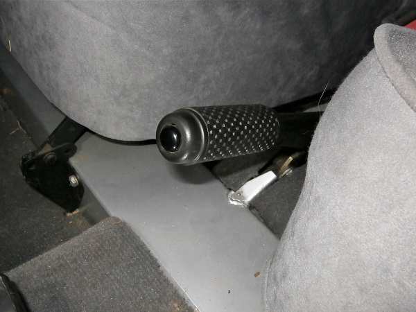
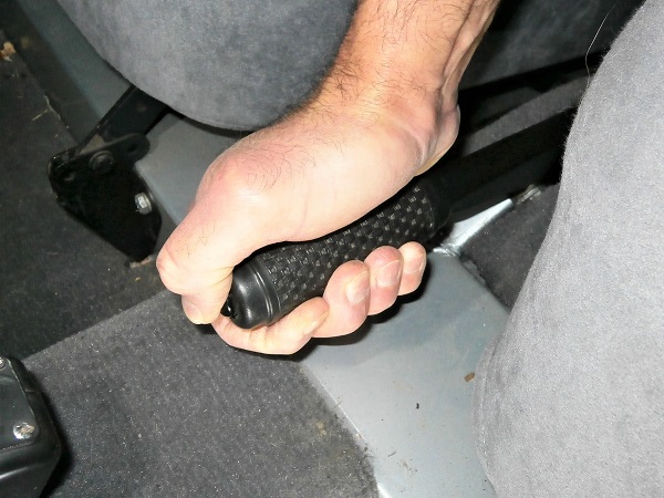
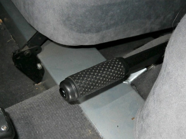
Release the handbrake.
Op 04
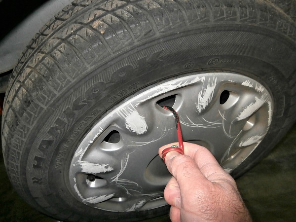
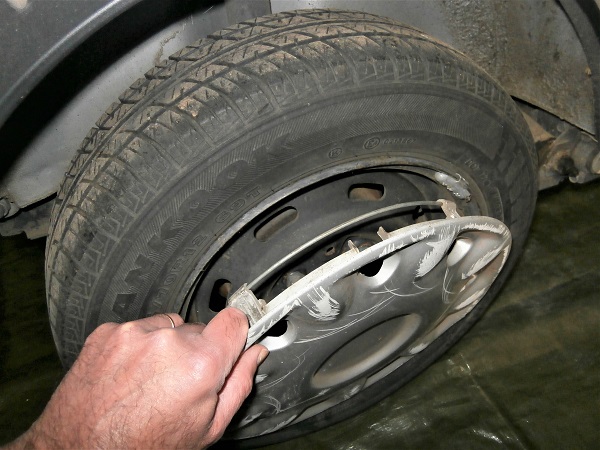
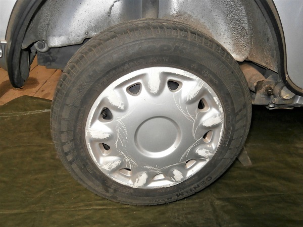
Remove the wheel trim. Pull with a hook.
Op 05
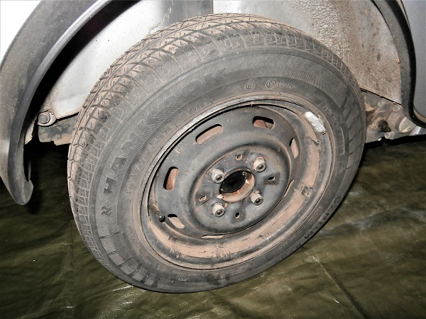
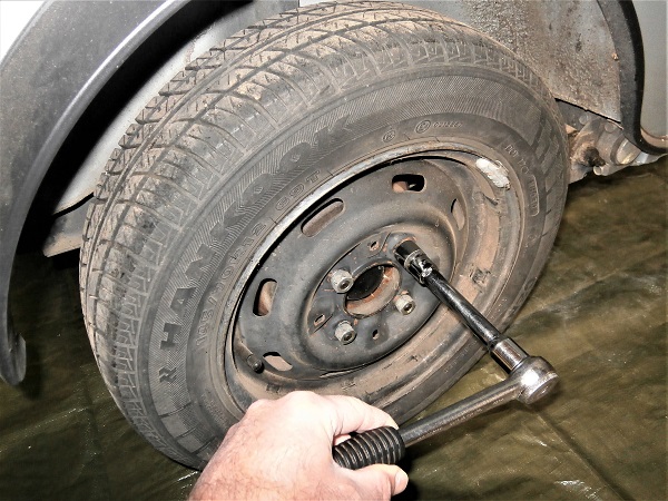
Slightly loosen the 4 wheel nuts. Use the 11/16'' socket.
Op 06
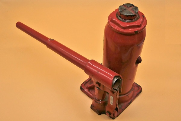
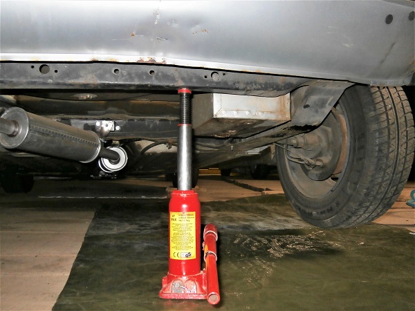
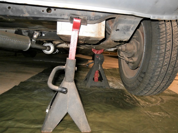
Lift the wheel. Use the jack.
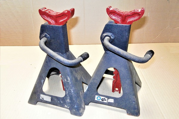
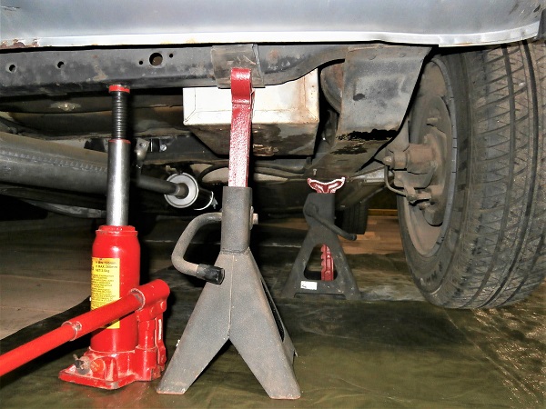
Fit jack stands or rigid chocks to guarantee your safety.
Before working under the vehicle, make sure to secure it properly with jack stands or rigid chocks. Never work under a vehicle supported only by a jack. It is too dangerous.
Op 07
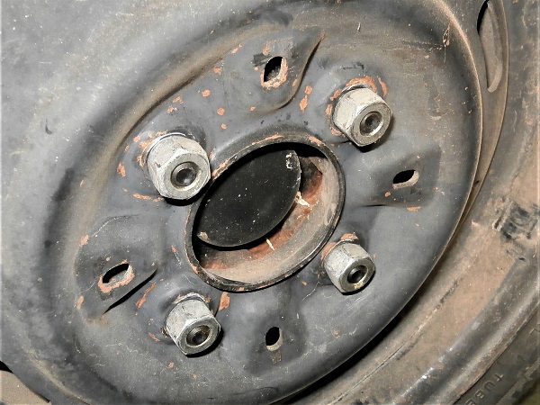
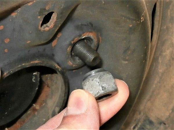
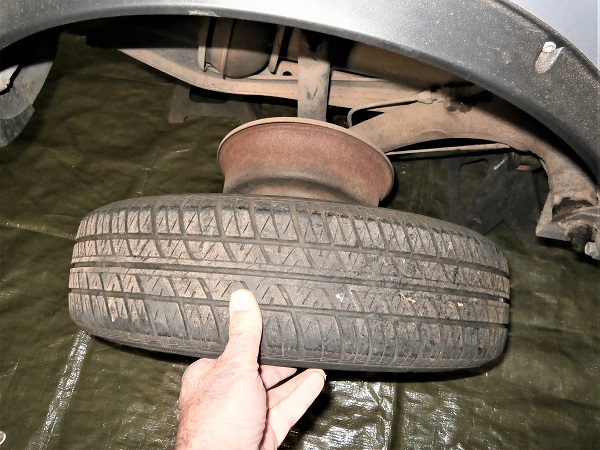
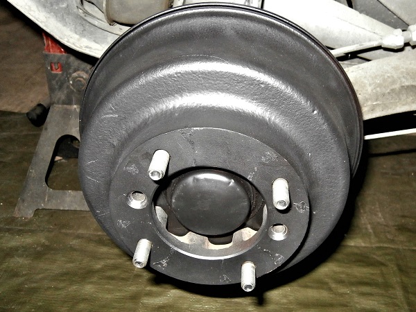
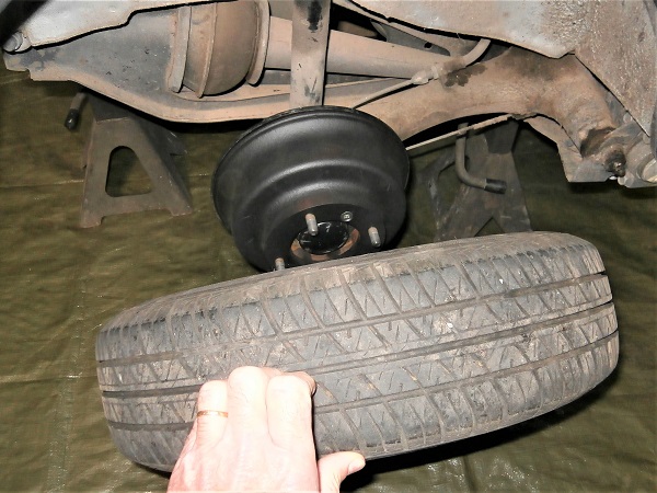
Remove the 4 wheel nuts. Unscrew by hand.
Remove the wheel. Pull by hand.
Op 08
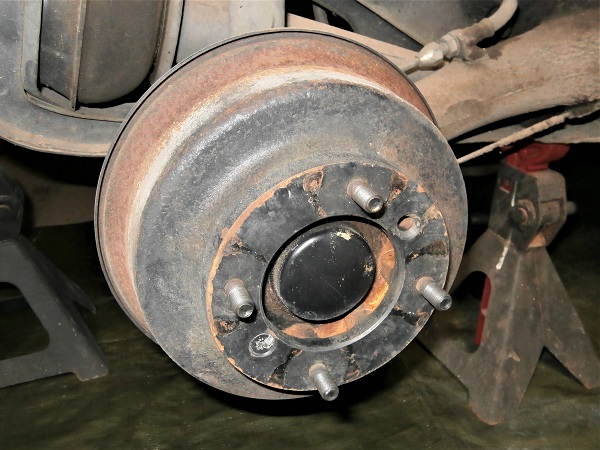
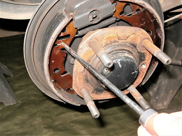
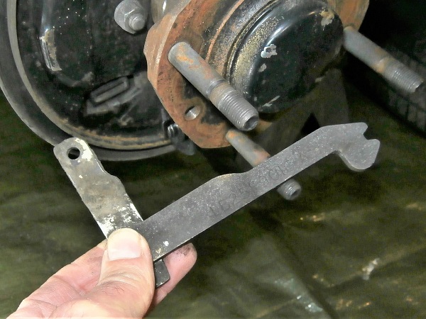
Immobilize the hub in rotation. Use a crowbar or a metal bar.
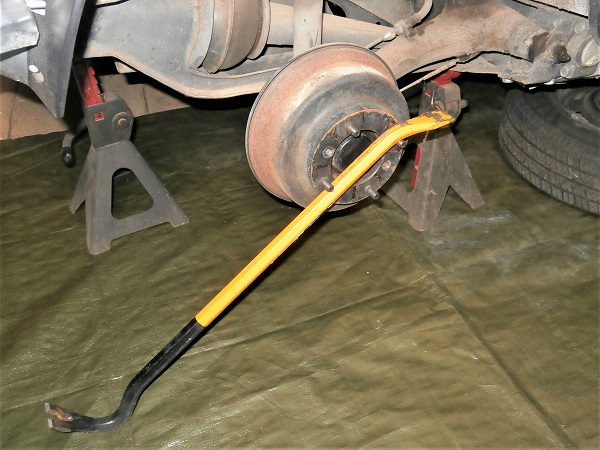
Op 09
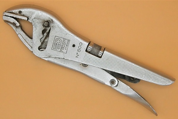
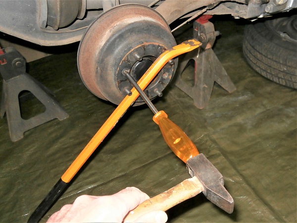
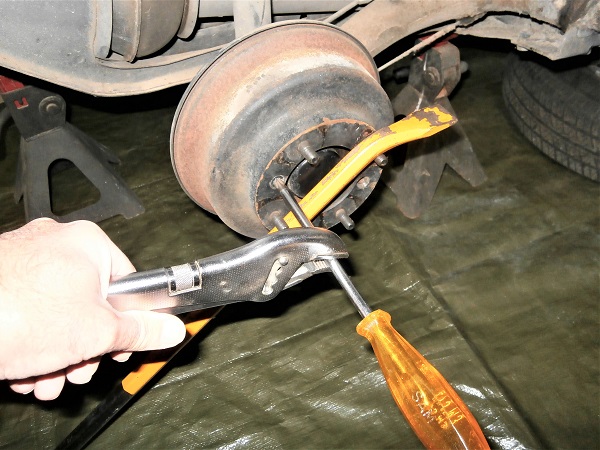
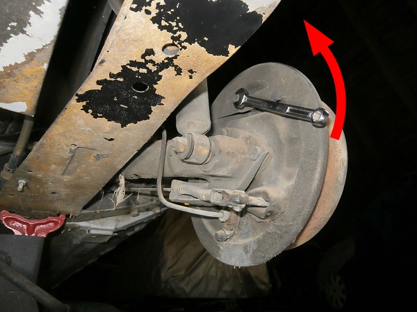
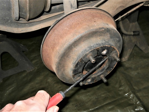
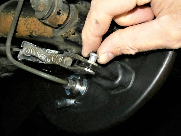
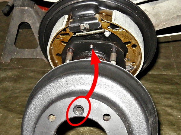
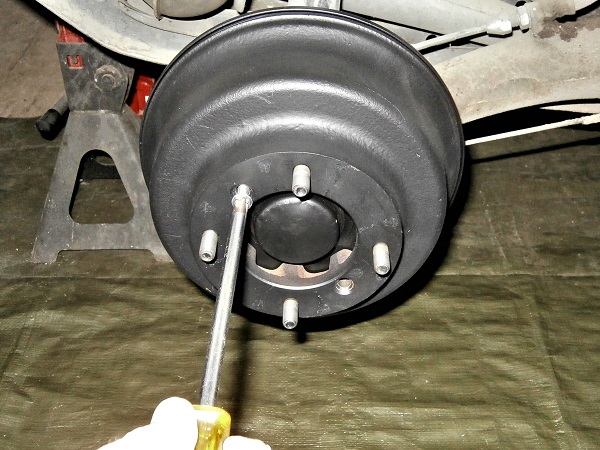
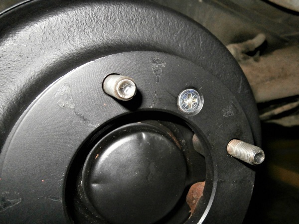
Unscrew the brake drum fixing screw. Use a Phillips screwdriver and locking pliers.
Use a Phillips screwdriver with a print perfectly adapted to the screw.
The brake drum fixing screw is frequently oxidized. Take every precaution to unscrew it without damaging its head. If unfortunately the screw head is damaged, you only have to use the drill to decapitate the screw and remove the drum.
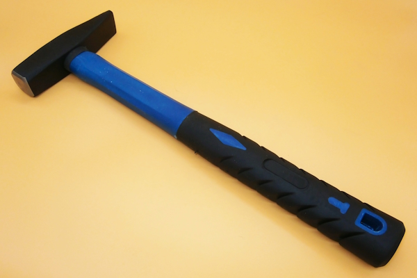
If the screw is blocked, tap a few hammer blows on the screwdriver handle (1st photo). This should loosen the threads.
Op 10
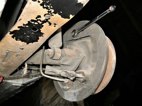
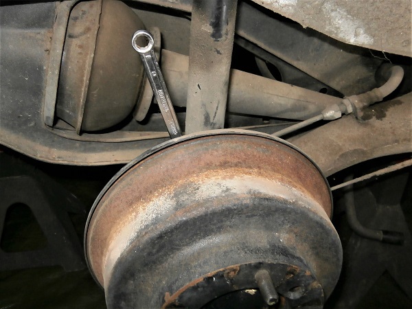
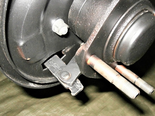
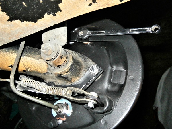
Loosen the brake adjuster screw. Use the 8 mm spanner.
If the screw is oxidized, spray penetrating oil and let it act.
If the screw head is rounded, use locking pliers (screwed for screwed). When the brake shoes are removed, you will be able to remove the screw and fit a new one.
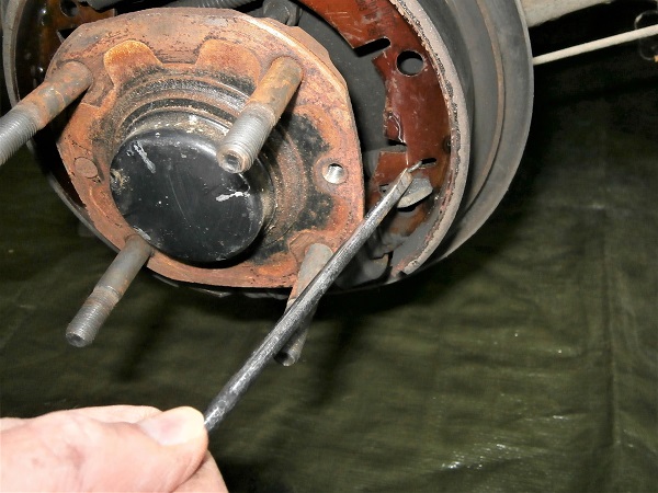
Op 11
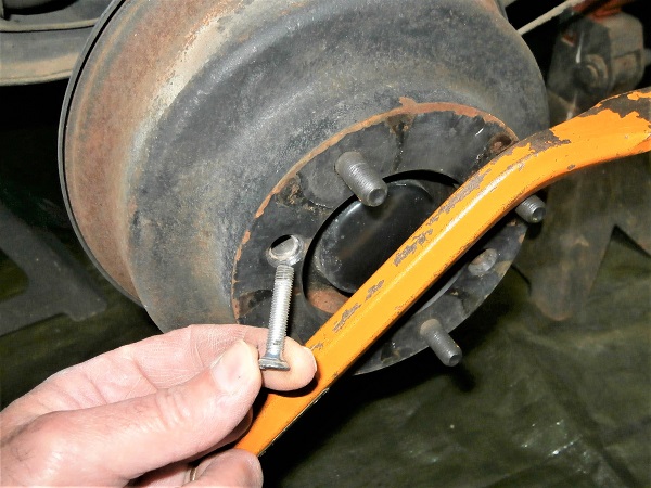
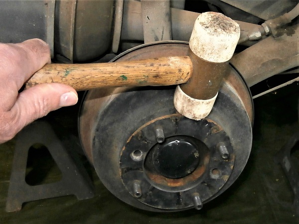
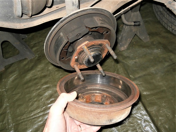
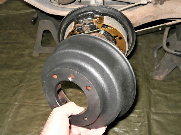
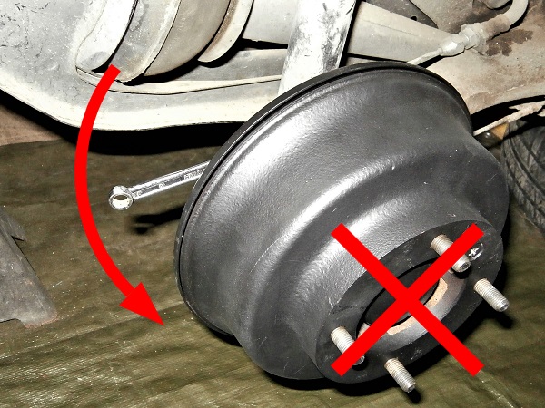
Remove the brake drum. Pull by hand.
If the brake drum does not come :
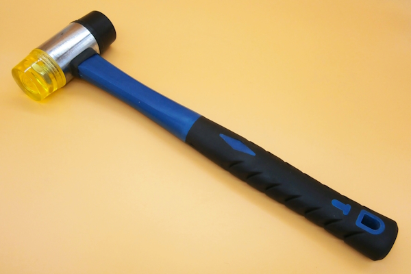
• Tap on the periphery of the drum with a mallet (1st photo).
• Pry with a flathead screwdriver (2nd photo).
• Tap on the periphery of the drum with a mallet (1st photo).
• Pry with a flathead screwdriver (2nd photo).
Remove the brake shoes
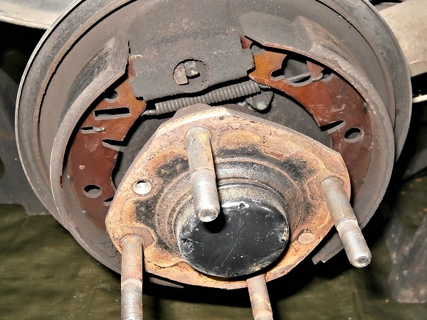
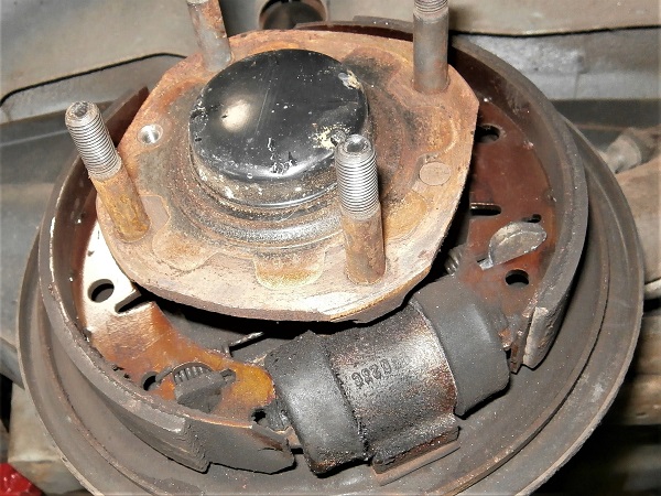
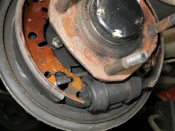
Op 12
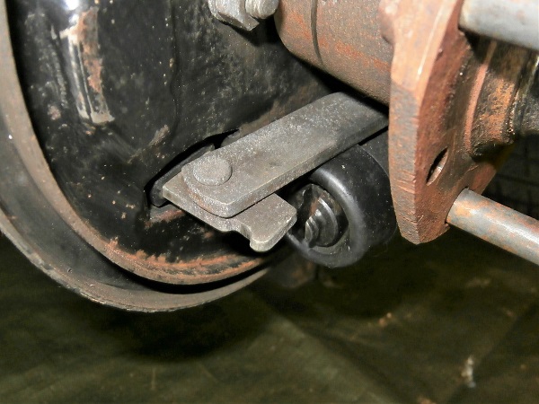
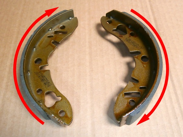
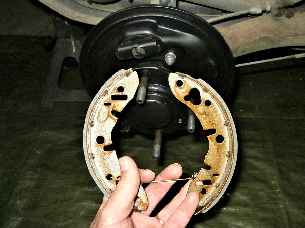
Analyze precisely the position of each of the elements (direction of the shoes, fixing point of the springs and handbrake lever). This will be useful for reassembly.
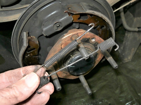
Op 13
Remove the 2 springs from the brake shoes. Use a flathead screwdriver.
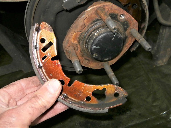
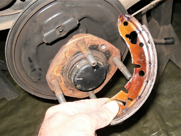
Op 14
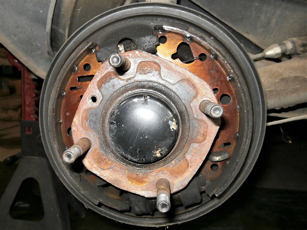
Remove the brake shoes. Pull by hand.
Ensure that the pistons do not come out of the wheel cylinder.
Op 15
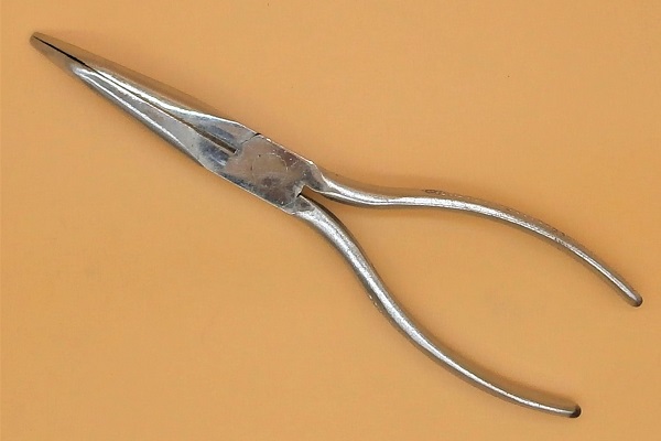
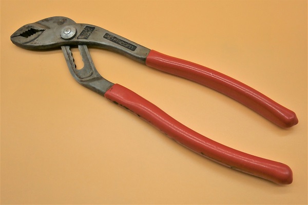
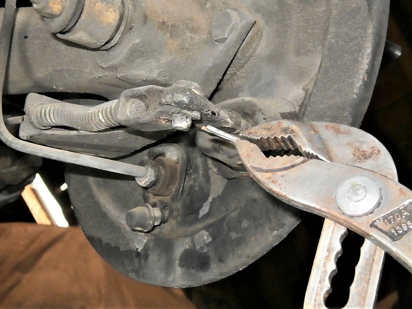
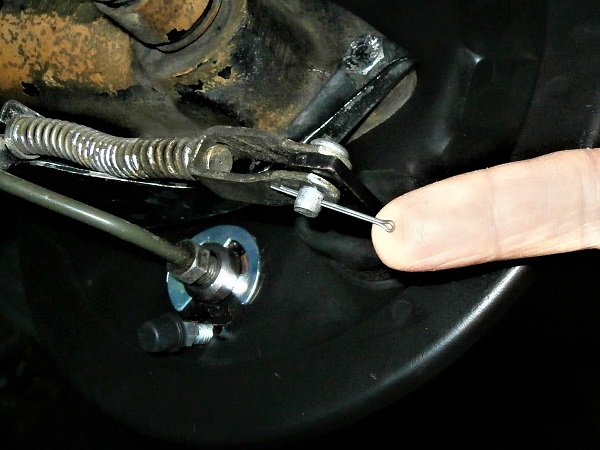
Remove the split pin and the handbrake lever pin. Use the multigrip pliers.
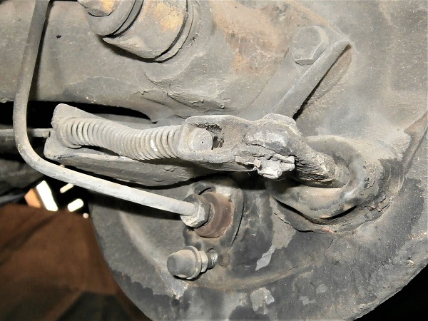
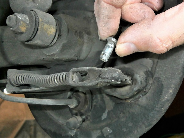
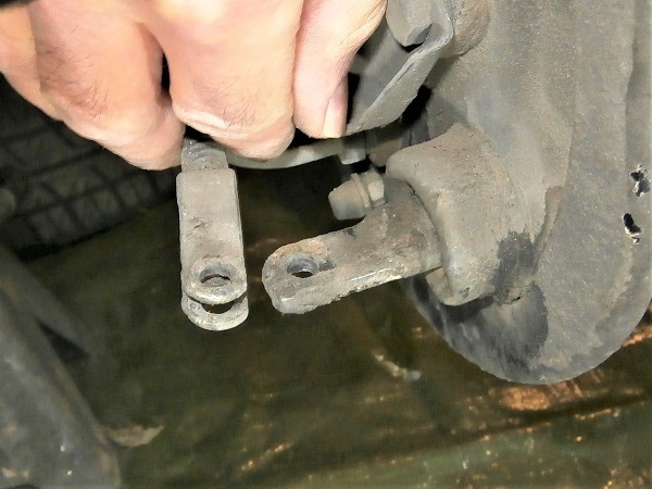
Op 16
Remove the handbrake lever. Pull by hand.
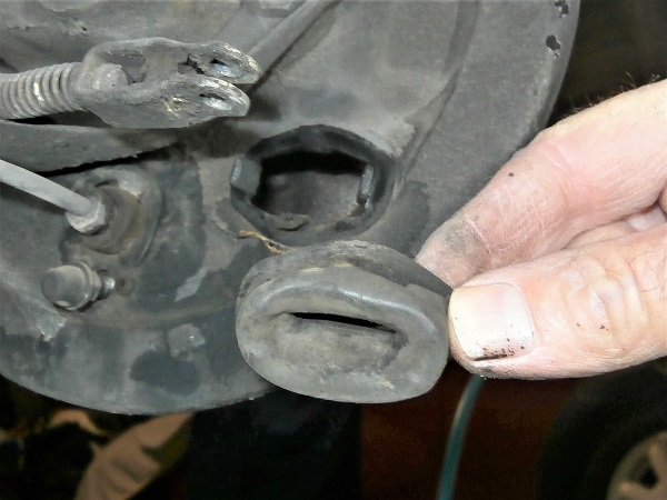
Op 17
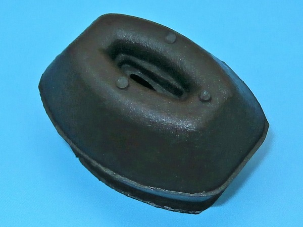
Remove the handbrake lever gaiter. Pull by hand.
Advertisement
Remove the wheel cylinder
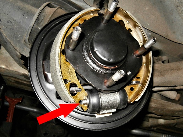
Op 18
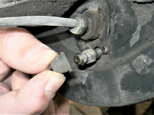
Remove the bleed nipple cap from the wheel cylinder. Pull by hand.
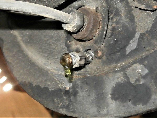
Slightly loosen the bleed nipple. Use the 8 mm spanner.
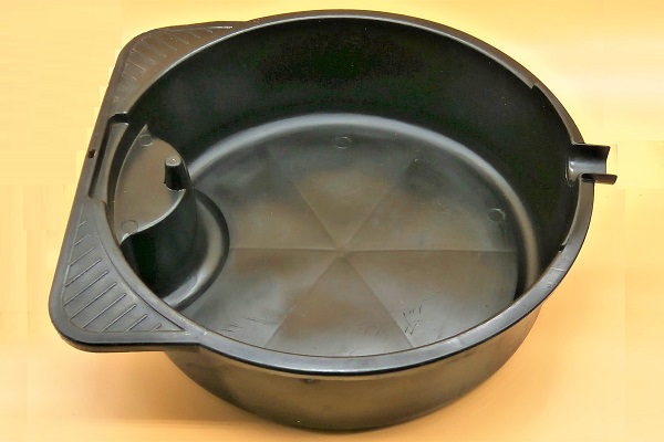
Let the brake fluid flow out.
Place a drain pan under the bleed nipple.
Op 19
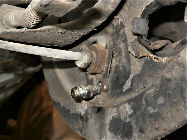
Remove the bleed nipple. Unscrew by hand.
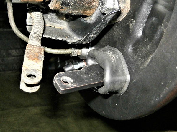
Op 20
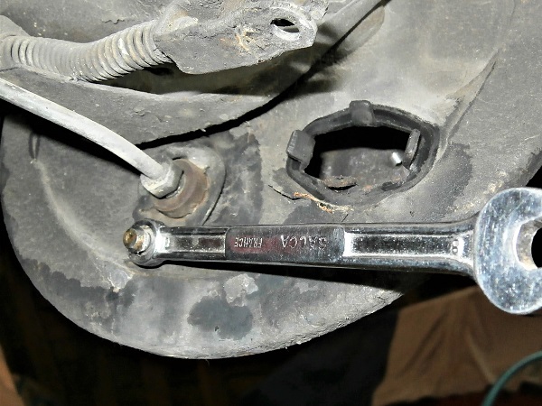
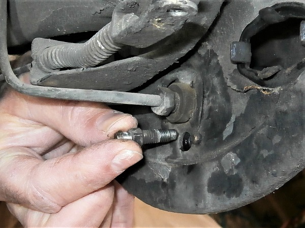
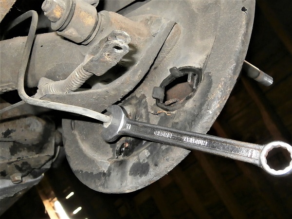
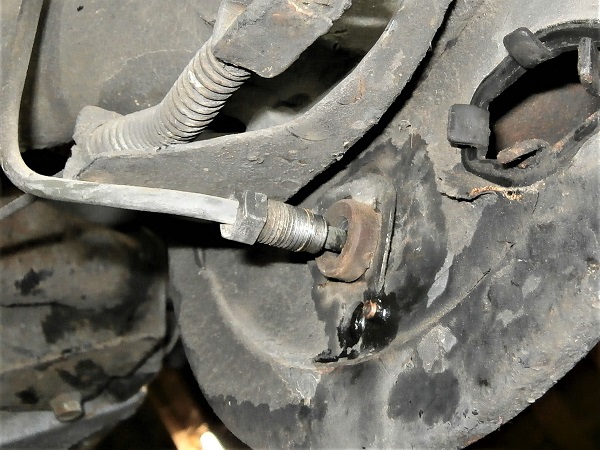
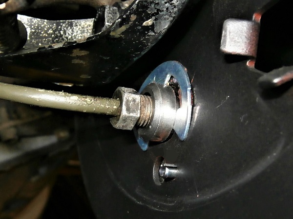
Unscrew the brake pipe end fitting from the wheel cylinder. Use the 11 mm spanner.
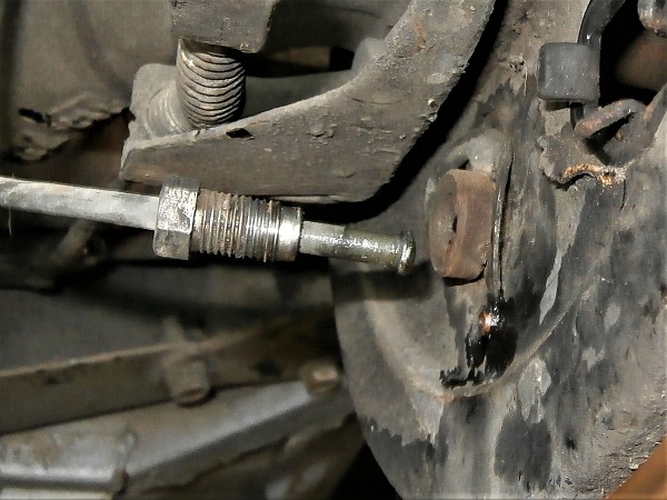
Slightly disengage the brake pipe. Pull by hand.
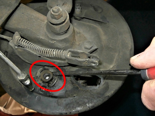
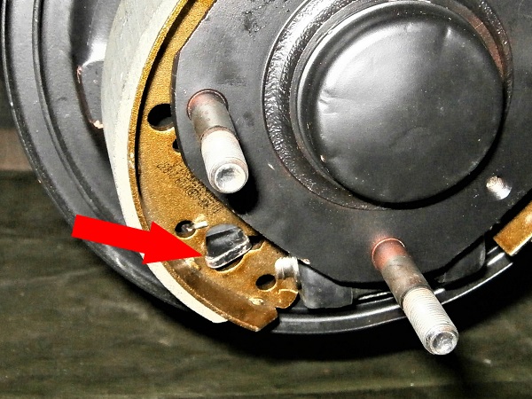
Op 21
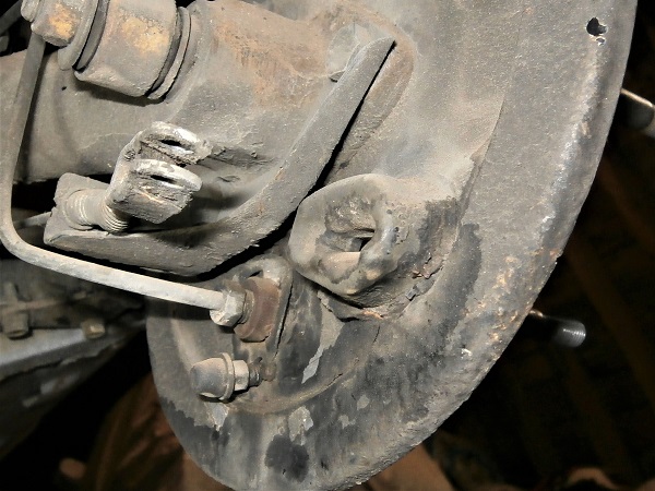
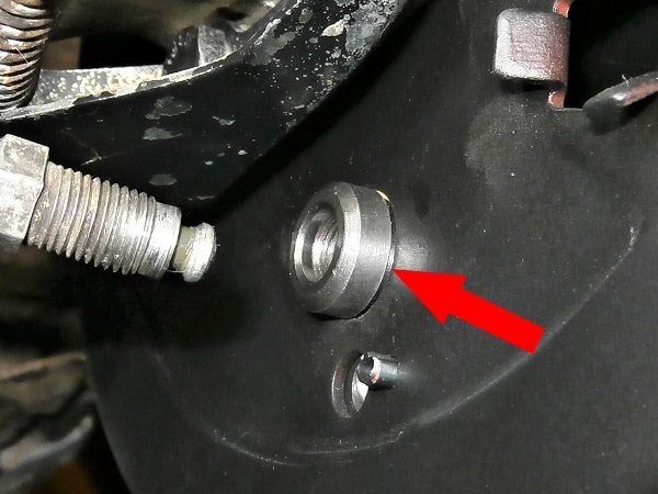
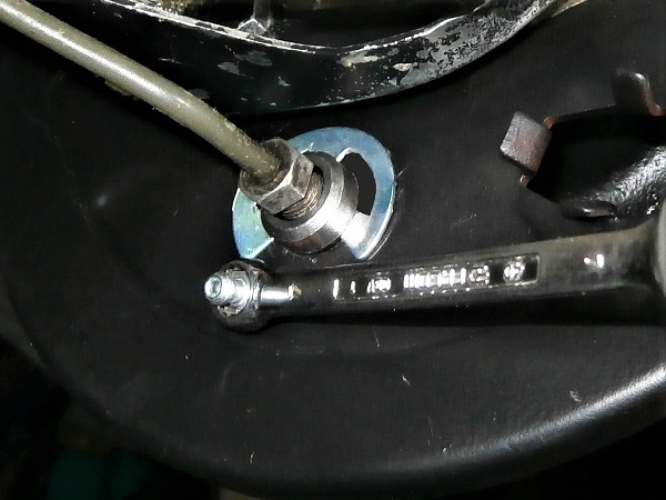
Remove the wheel cylinder retaining circlip. Use a flathead screwdriver.
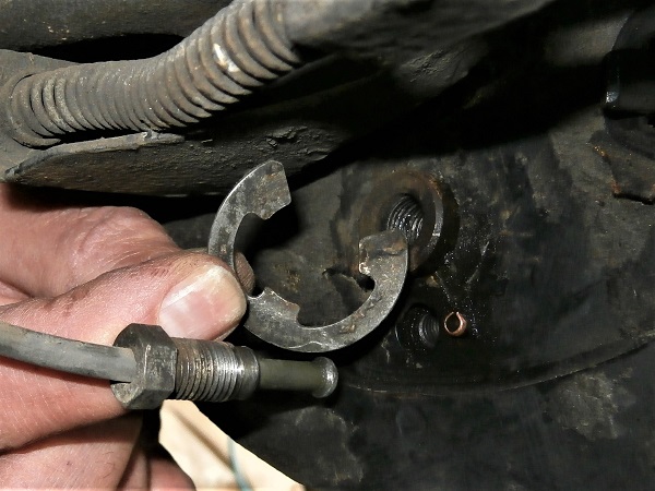
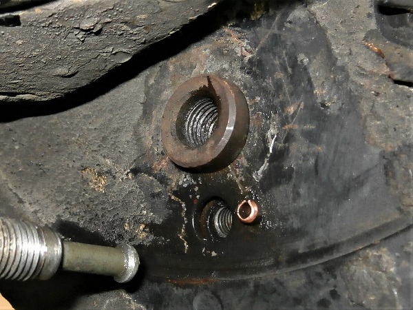
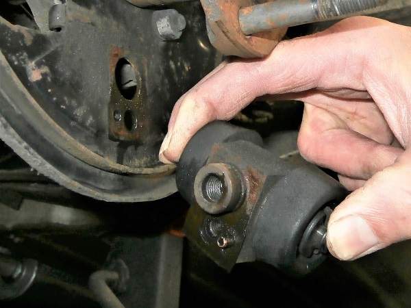
Op 22
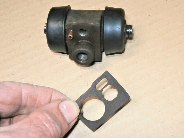
Remove the wheel cylinder. Pull by hand.
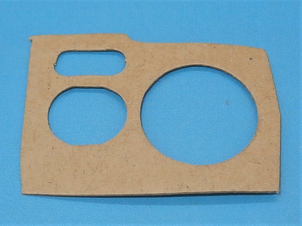
Recover the wheel cylinder backplate gasket and throw it in the trash (3rd photo).
Fit the wheel cylinder
Op 23
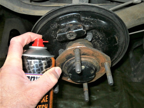
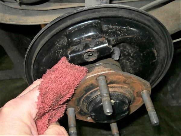
Clean the backplate and hub. Use brake cleaner and a cloth.
Never use compressed air when cleaning the brake system. You could inhale very harmful dust. Use brake cleaner and a cloth. Your lungs will thank you.
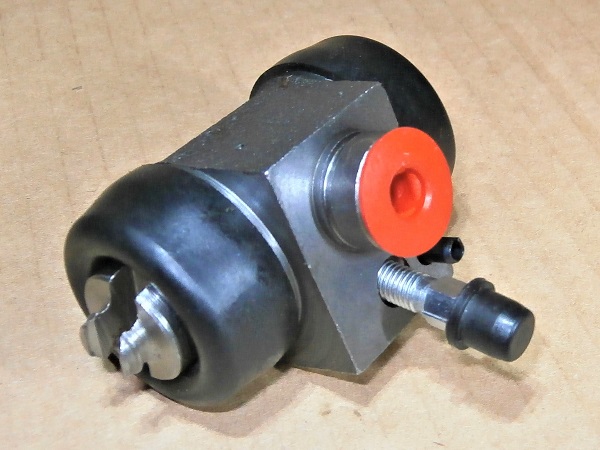
Op 24
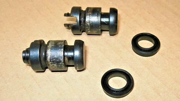
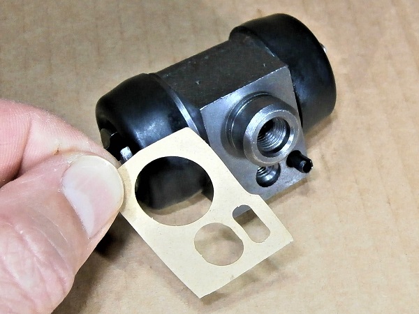
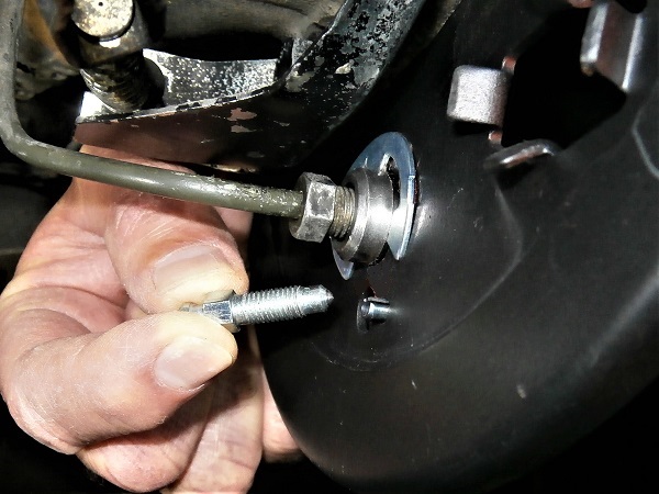
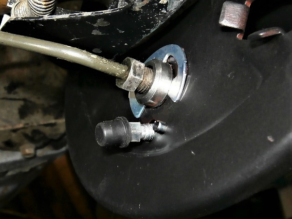
Remove the plug and bleed nipple from the new wheel cylinder (GWC1102). Use the 7 mm spanner.
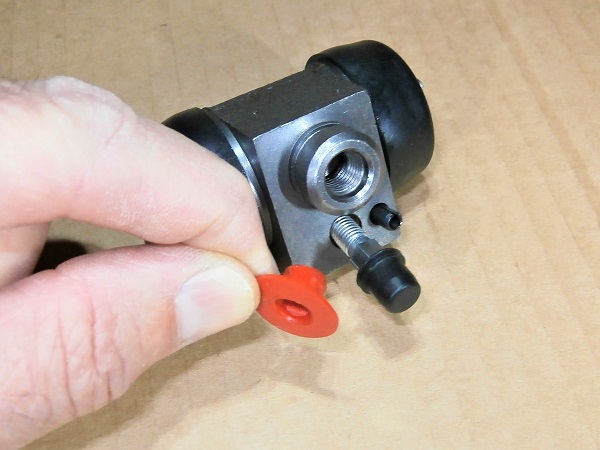
Op 25
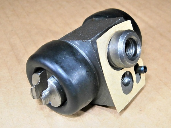
Fit the new gasket (37H4642) on the wheel cylinder
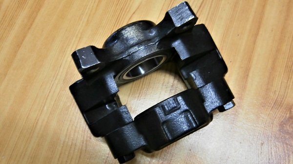
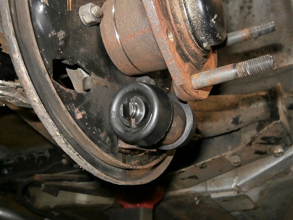
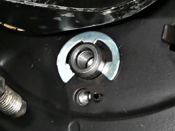
Op 26
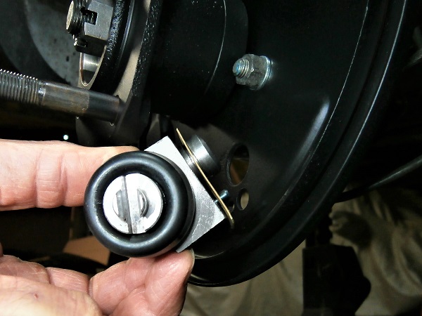
Fit the wheel cylinder on the backplate. Press by hand.
Check that the groove of the wheel cylinder protrudes from the other side of the backplate (3rd photo). This is where we will fit the circlip.
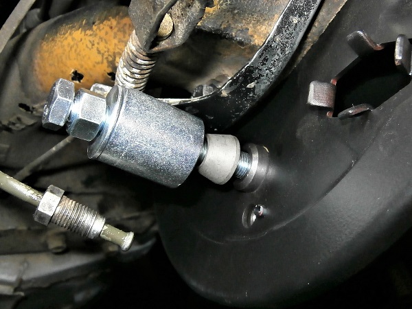
Op 27
Fit the new circlip (17H7949) :
•
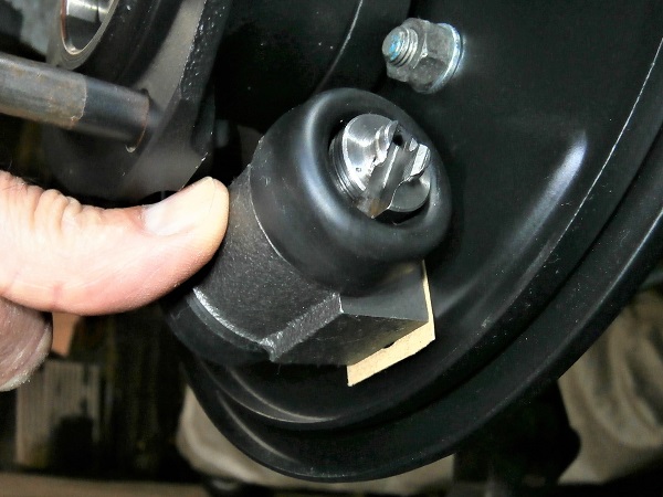
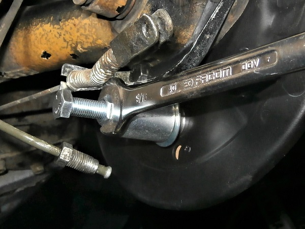
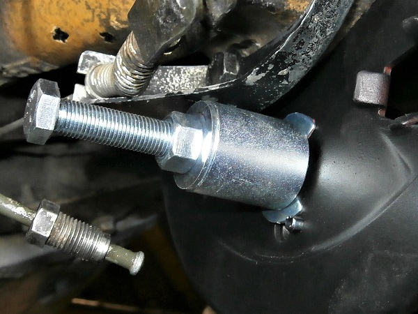
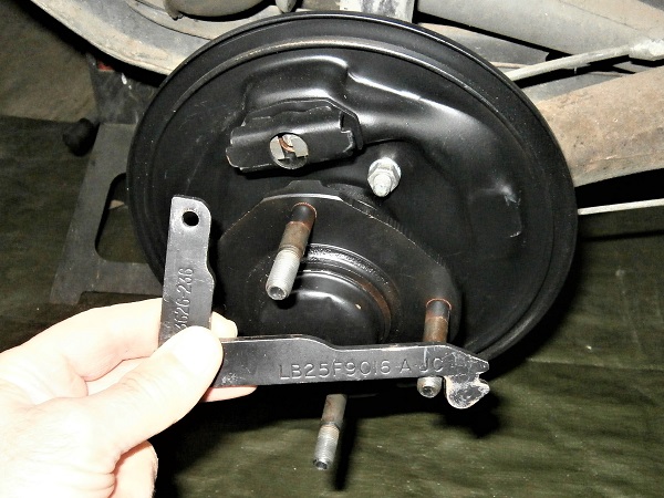
Screw the bolt of the Tool14 into the wheel cylinder (1st photo). Screw by hand.
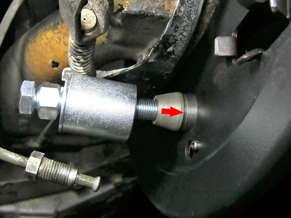
•
Press the guide cone against the wheel cylinder (2nd photo). Screw by hand.
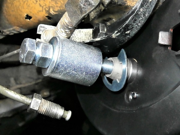
•
Fit the circlip on the guide cone (3rd photo).
•
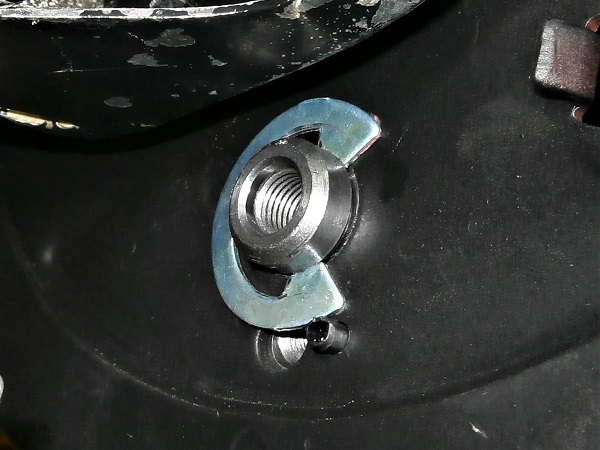
Screw the nut and push the circlip into the groove of the wheel cylinder (4th and 5th photo). Use the 9/16'' spanner.
•
Remove the Tool14.
The Tool14 is not essential for positioning the wheel cylinder circlip. You can simply use the multigrip pliers. But the circlip is really very rigid and without the tool, it is very difficult to fit.
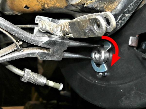
Op 28
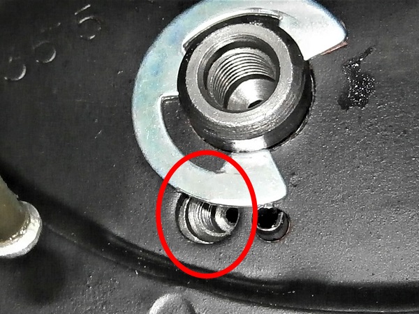
Rotate the circlip to release the bleed nipple port. Use needle-nose pliers.
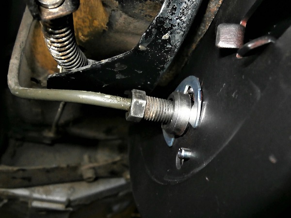
Op 29
Fit the brake pipe in the wheel cylinder and screw on the end fitting. Use the 11 mm spanner.
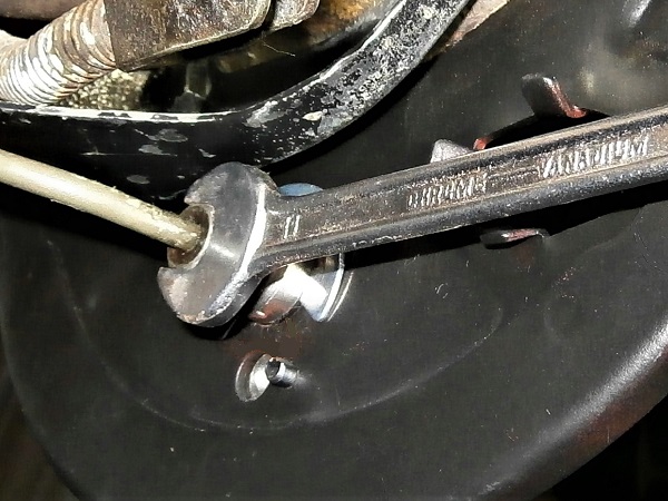
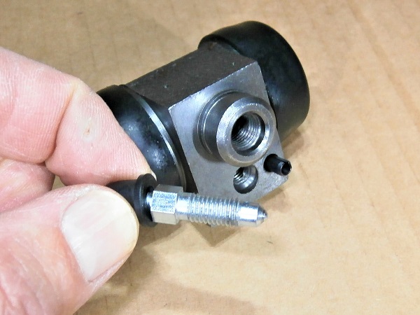
Op 30
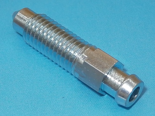
Screw the bleed nipple (513118A) onto the wheel cylinder. Use the 8 mm spanner.
Fit the brake shoes
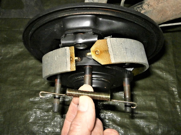
Op 31
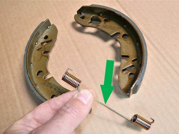
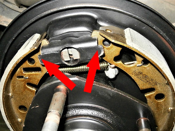
Fit the lower spring (kit GBK1834) on the brake shoes (GBS834AF).
Respect the positioning of the shoes. They must be head-to-toe (1st photo).
The spring connection wire must be positioned downwards (2nd photo).
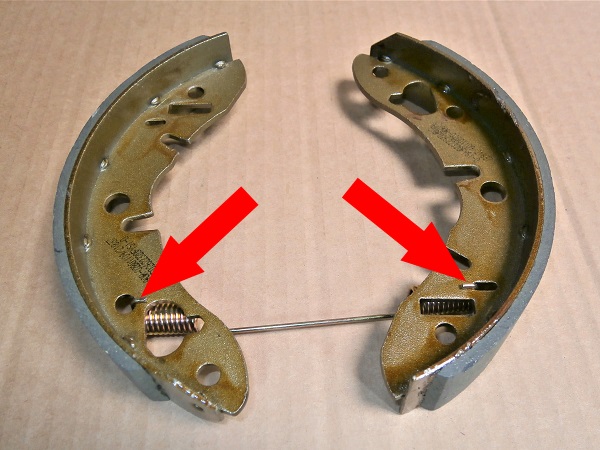
Respect the spring attachment points (3rd photo).
Op 32
Fit the handbrake lever on the backplate.
Op 33
Fit the brake shoes + lower spring assembly on the backplate :
•
Fit the front shoe on the wheel cylinder (2nd photo).
•
Fit the handbrake lever in the front shoe (3rd photo).
•
Fit the rear shoe on the wheel cylinder (4th photo).
•
Fit the handbrake lever in the rear shoe (5th photo).
Op 34
Fit the upper spring (kit GBK1834) on the shoes (2nd photo).
Fit the shoes on the adjuster system (3rd photo).
Respect the spring attachment points (2nd photo).
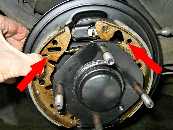
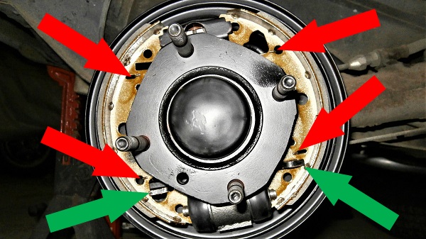
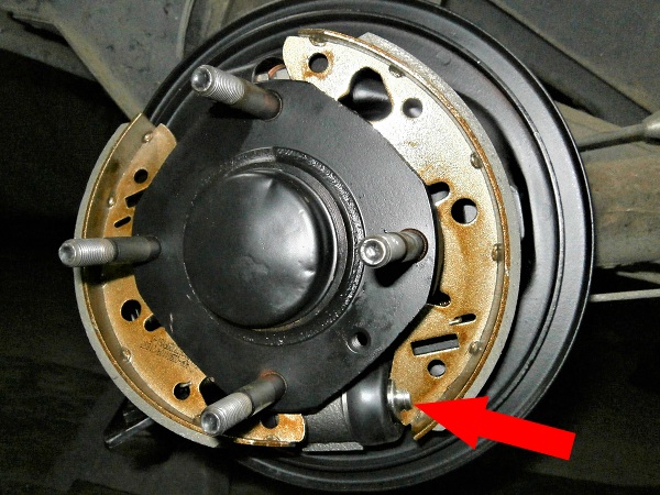
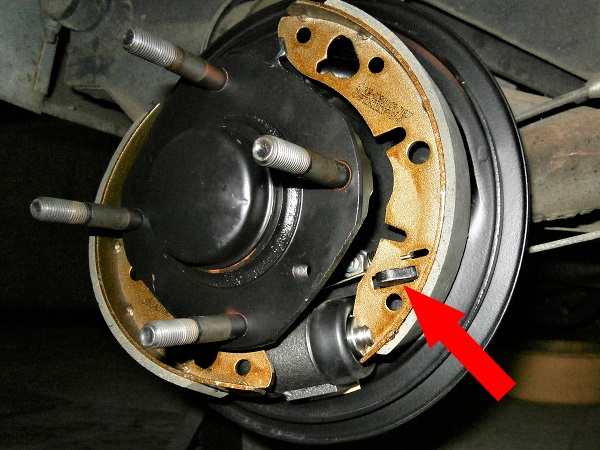
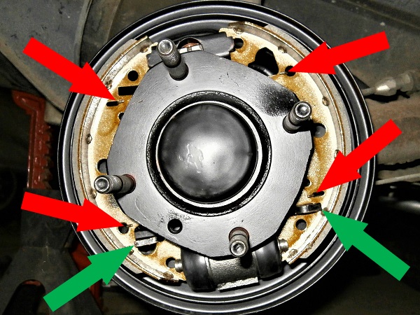
Op 35
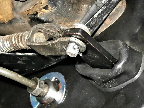
Before reassembling the drum, check the correct position of the springs anchor points (red arrows) and the handbrake lever (green arrows).
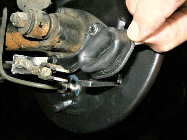
Op 36
Fit the handbrake lever gaiter (17H7612).
Op 37
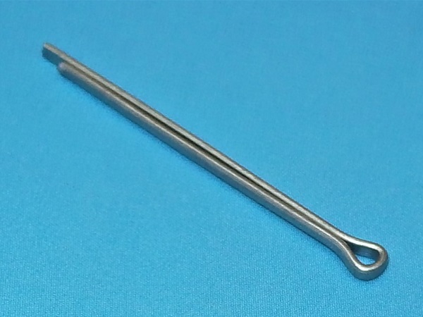
Fit the handbrake lever pin and its split pin (GFK101).
Spread the legs of the split pin. Use the multigrip pliers.
Advertisement
Fit the brake drum
Op 38
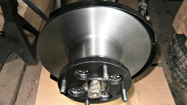
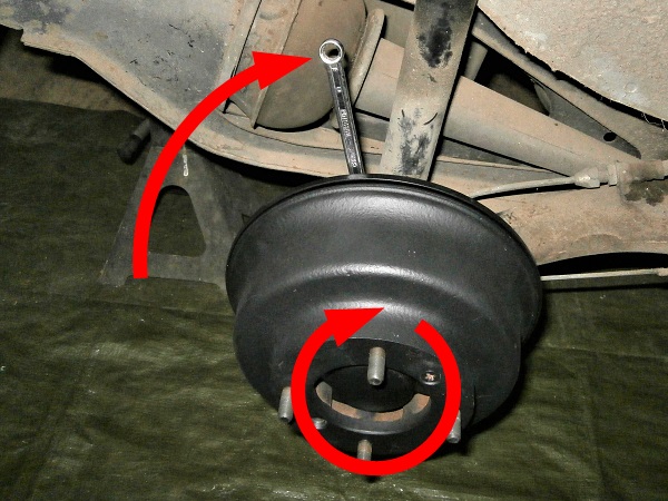
Fit the drum. Push by hand.
Align 1 of the 2 drum holes with the hub tapping (2nd photo). This will allow you to fit the screw.
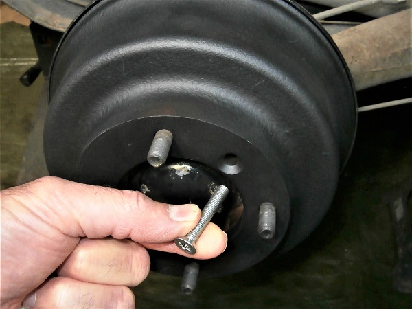
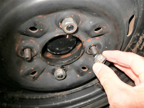
Op 39
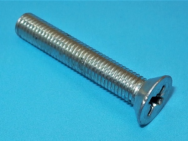
Screw in the drum fixing screw (CMZ422). Use the Phillips screwdriver.
Op 40
Adjust the shoe clearance. Use the 8 mm spanner :
•
Screw in the brake adjuster screw until the drum is completely blocked (2nd photo).
•
Loosen the screw until the drum can rotate freely (3rd photo).
Op 41
Fit the wheel :
•
Fit the wheel on the drive flange.
•
Screw on the 4 nuts. Use the 11/16'' socket.
•
Lower the Mini to the ground. Remove the jack stands.
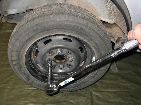
•
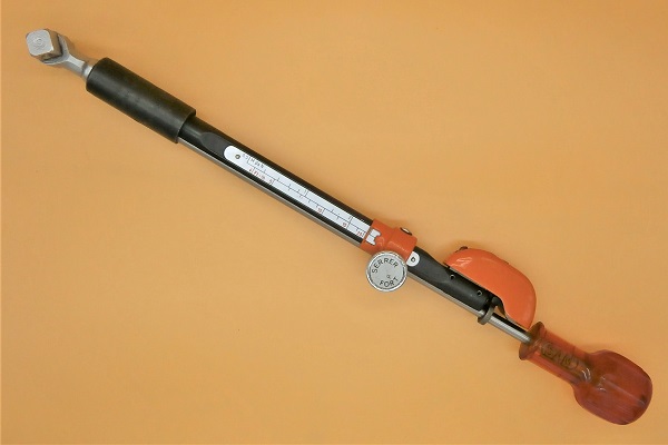
Tighten the 4 nuts to the torque corresponding to the type of rim. Use the torque wrench.
The tightening torque of the wheel nuts is :
• 63 mN for steel rims.
• 50 mN for alloy rims.
• 63 mN for steel rims.
• 50 mN for alloy rims.
Op 42
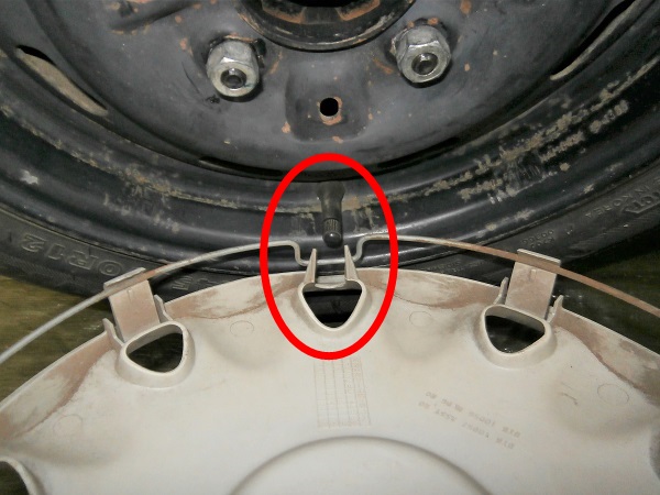
Fit the wheel trim. Fit it into the rim by pushing by hand.
Position the notch of the wheel trim at the valve (1st photo).
Op 43
Bleed the brake system (➔ see the tutorial ''Brake system bleeding'').
The End