
This tutorial is also available in French
➔

Heater control cable change on Austin Mini
Vehicle ➔ Mini 1000 year 1988
Difficulty ➔ Easy

Time ➔ 2 hours
Summary
Advertisement
Advertisement

Recommendations

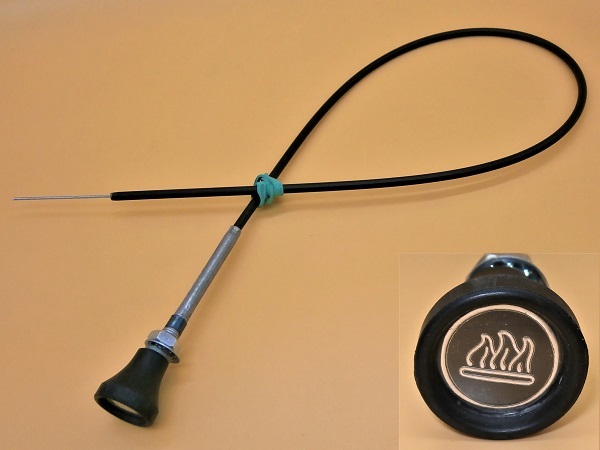
What we have called ''heater control cable'' is actually a piano wire. We did this to simplify the reading of this tutorial because you will see that the word comes up often.
The manufacturer has provided a piano wire because the heater control must both pull and push on the heater valve. A cable would not have done the trick because it is designed only to pull.
The piano wire is extremely rigid. Avoid bending it at all costs, otherwise it will no longer slide in its housing.
There are 4 different heater control cables :
• CHM373 : for Mini from 1969 to 1988 (valve fixed to the cylinder head).
• JFF10003 : for Mini from 1988 to 1992 (valve on the hose).
• JFF10051 : for Mini SPI.
• JFF100910 : for Mini MPI.
Be sure to check the model before placing the order.
• CHM373 : for Mini from 1969 to 1988 (valve fixed to the cylinder head).
• JFF10003 : for Mini from 1988 to 1992 (valve on the hose).
• JFF10051 : for Mini SPI.
• JFF100910 : for Mini MPI.
Be sure to check the model before placing the order.
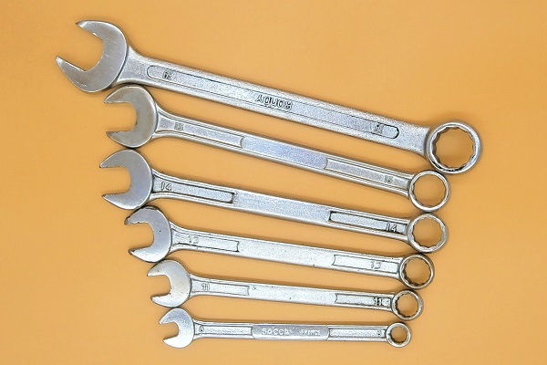
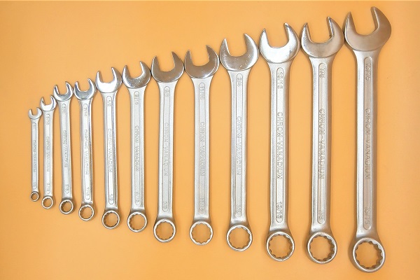
Required Tools
Sponsored links by

Spare Parts
Our Partners


Packaging :
•
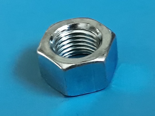
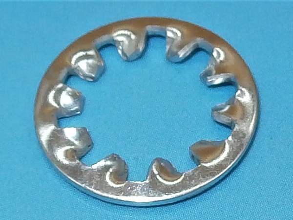
CHM373 : The heater control cable is sold with the GFK3213 nut and the GHF323 washer.
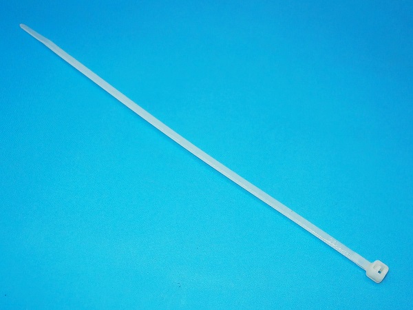
• Apart from the cable ties, all the parts above are sold individually.
• Apart from the cable ties, all the parts above are sold individually.
Advertisement
Remove the heater control cable
Op 01
Remove the air filter box (➔ see the tutorial ''HS4 air filter change'' Op 01 to 02).
Op 02
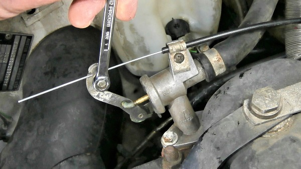
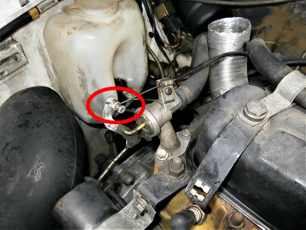
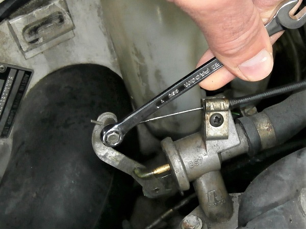
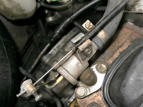
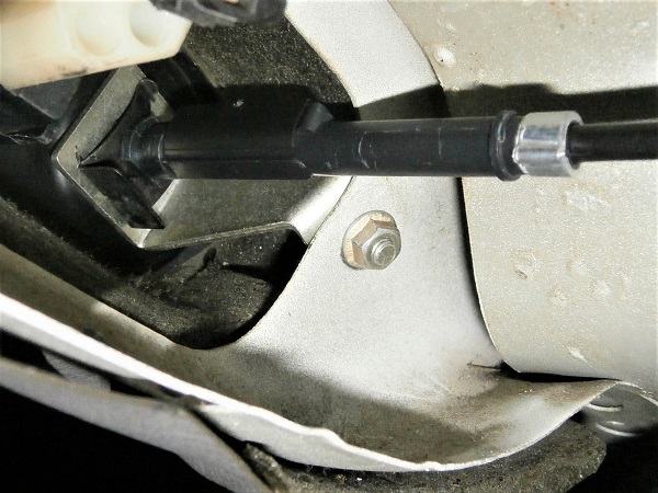
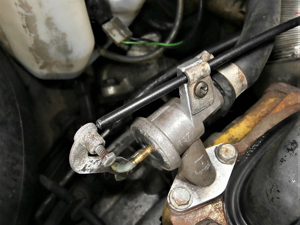
Unscrew the cable clamp bolt from the heater valve. Use a 1/4'' spanner.
No need to remove the bolt. Just make sure the cable can slide.
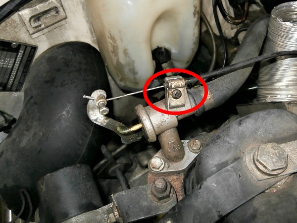
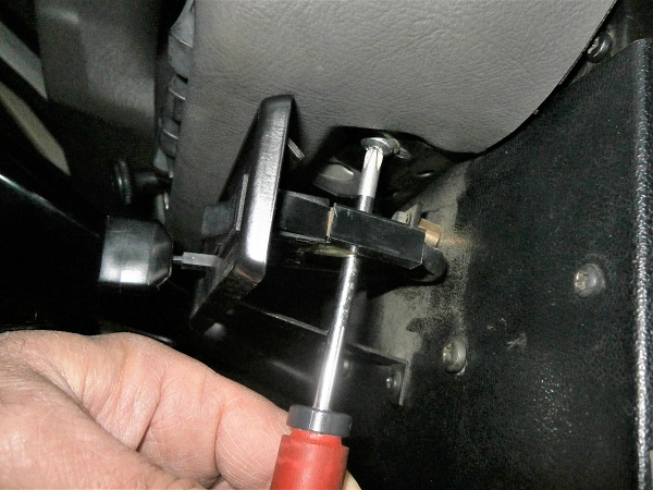
Op 03
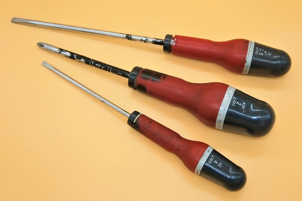
Unscrew the cable support bracket. Use a Phillips screwdriver.
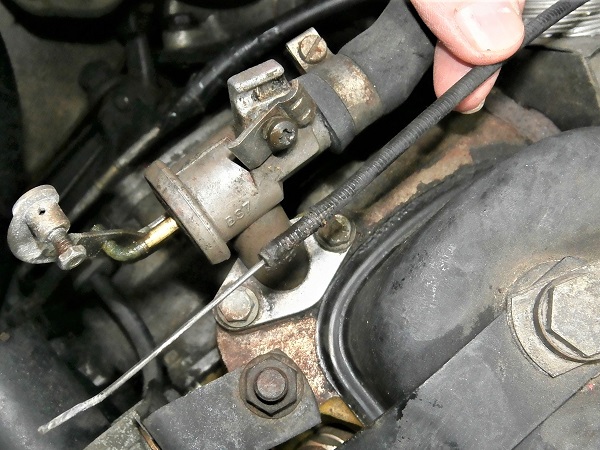
Op 04
Release the cable. Pull by hand.
Op 05
Locate the 2 fixing screws of the heater unit.
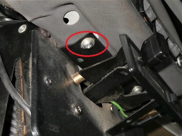
Op 06
Unscrew the 2 heater unit fixing screws. Use the Phillips screwdriver.
Op 07
Lower the heater unit. Push by hand.

Be careful not to stretch the electrical wires or the hoses.
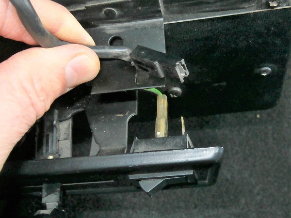
Op 08
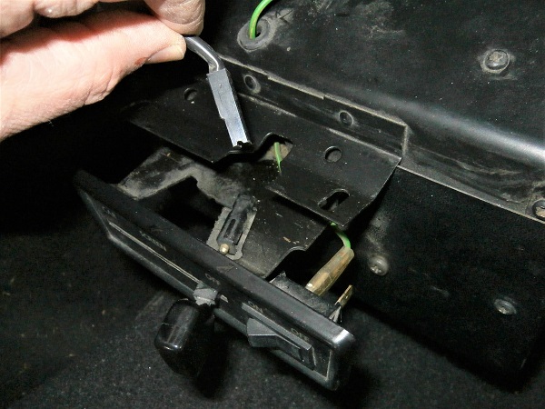
Disconnect the electrical wire from the heater fan switch. Pull by hand.
Disconnect only the black wire which is stretched. No need to disconnect the green wire.
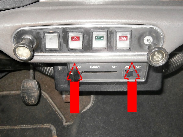
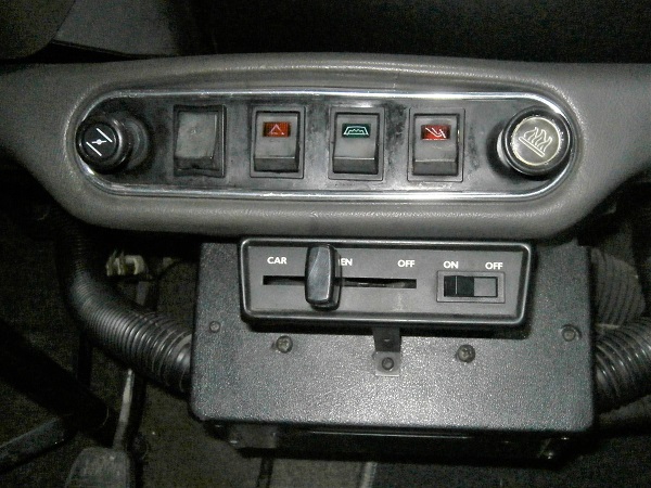
Op 09
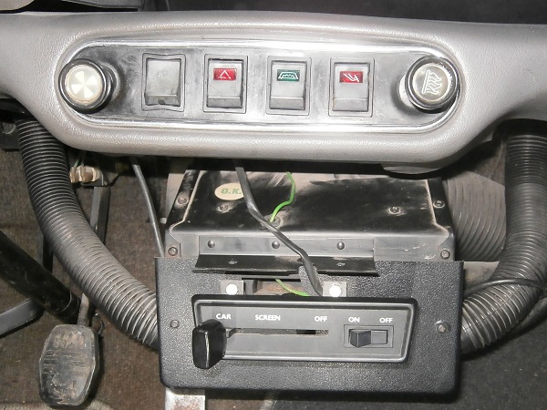
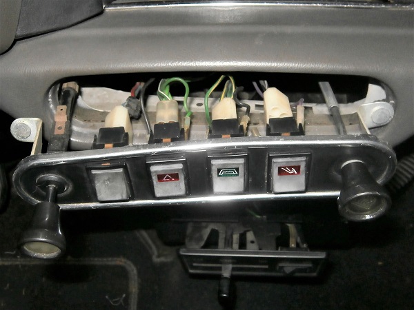
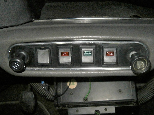
Locate the 2 fixing nuts of the switch panel.
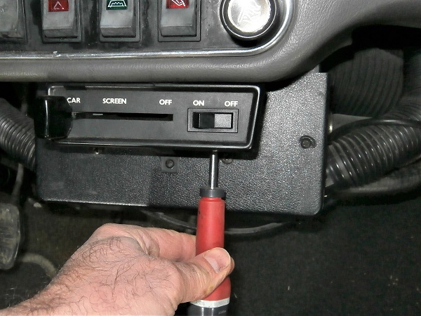
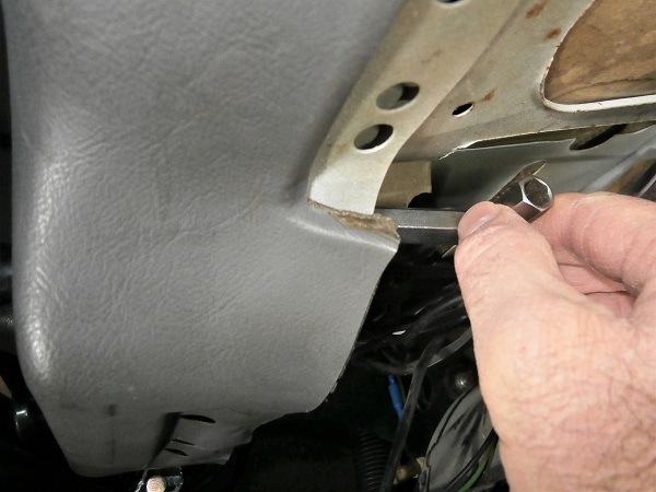
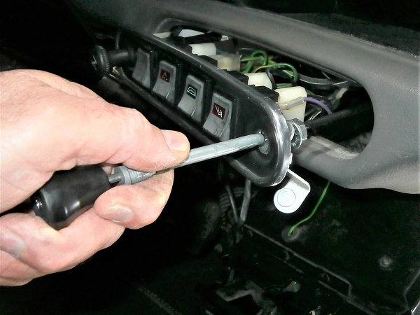
Op 10
Unscrew the 2 switch panel fixing nuts. Use the 8 mm socket spanner.
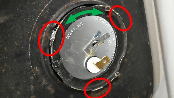
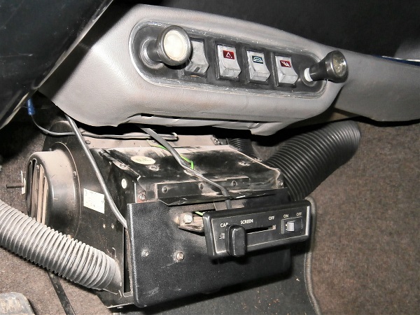
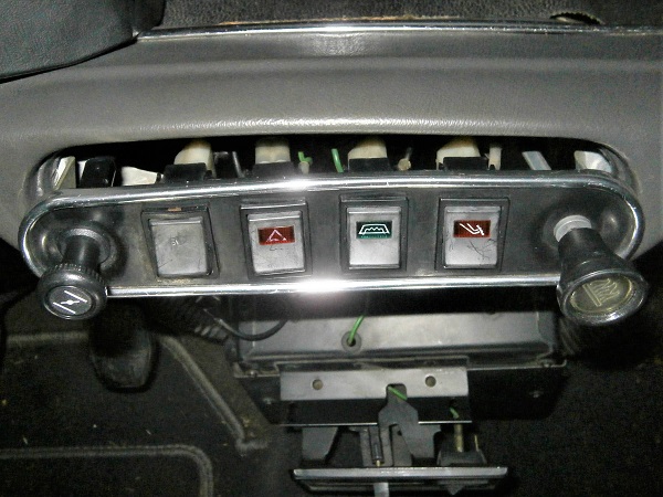
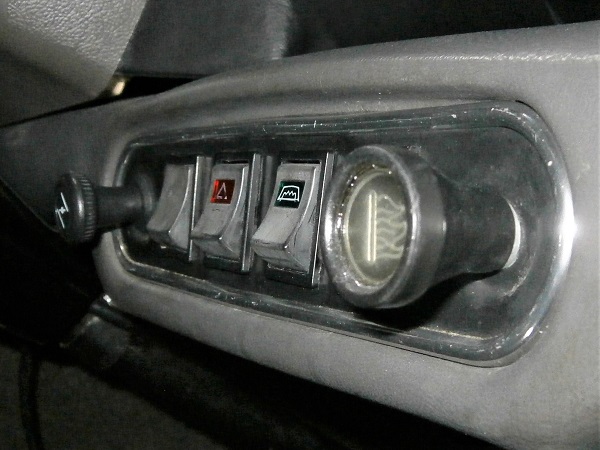
Op 11
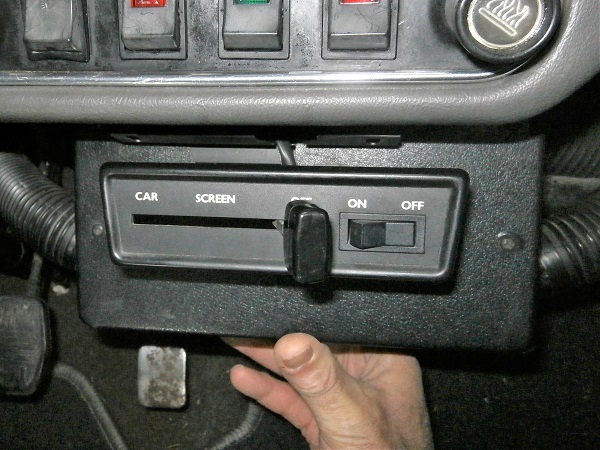
Disengage the switch panel. Pull by hand.
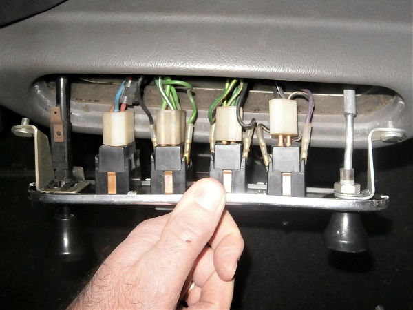
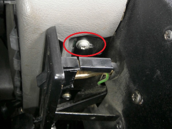
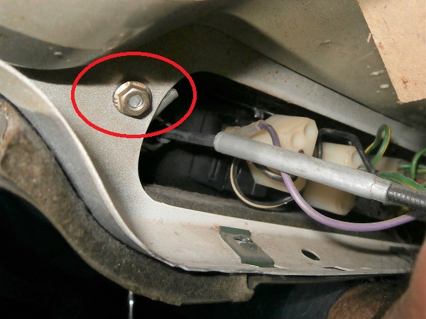
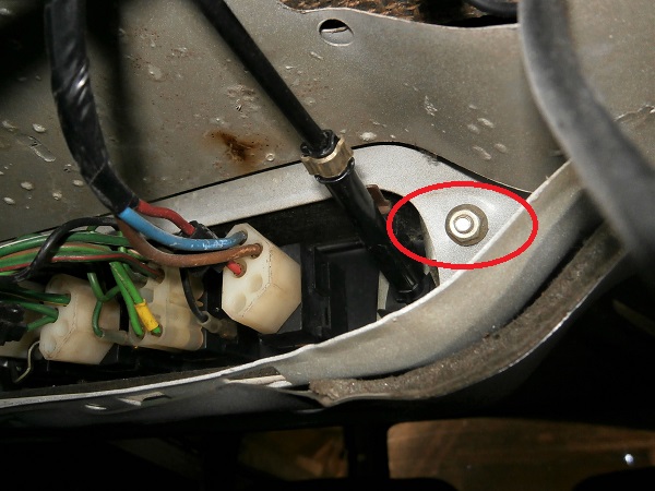
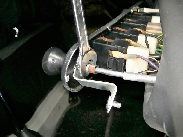
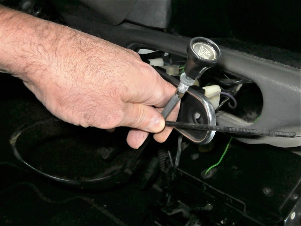
Op 12
Unscrew the heater control fixing nut. Use the 14 mm spanner.
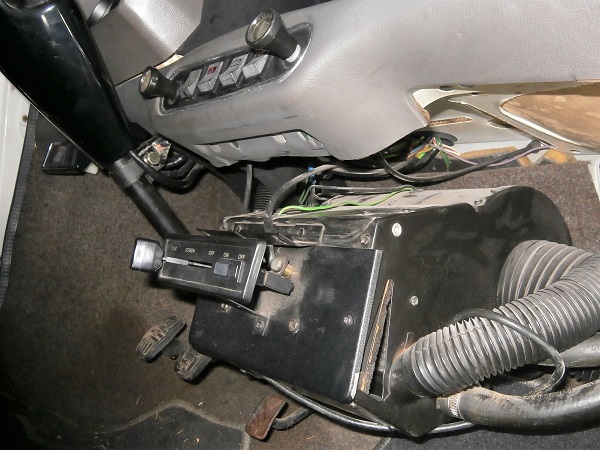
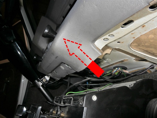
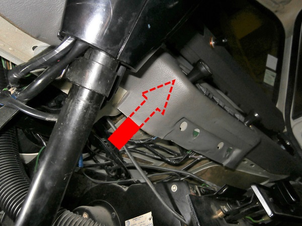
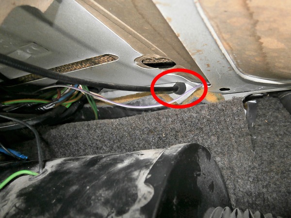
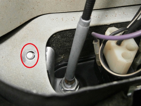
Op 13
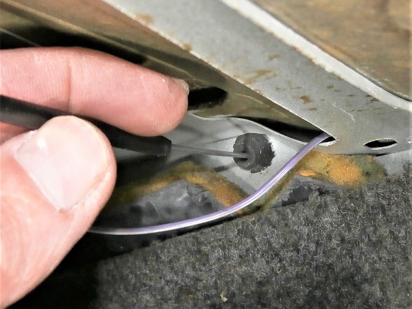
Look under the dashboard and locate where the heater control cable passes through the bulkhead.
This may be useful when you will have to pass the new cable through.
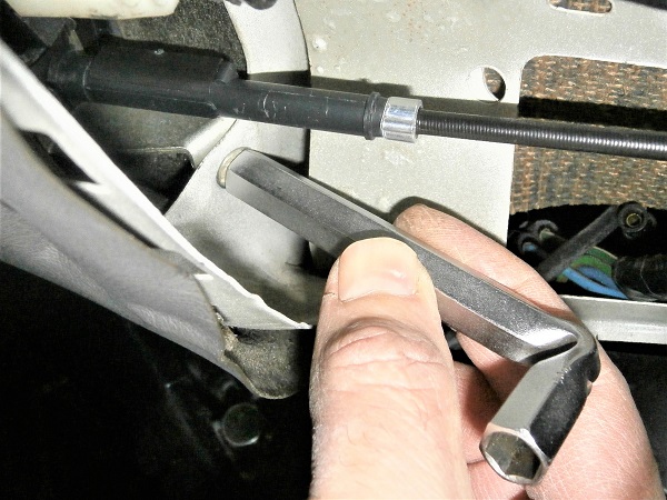
Op 14
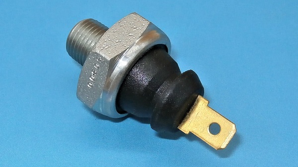
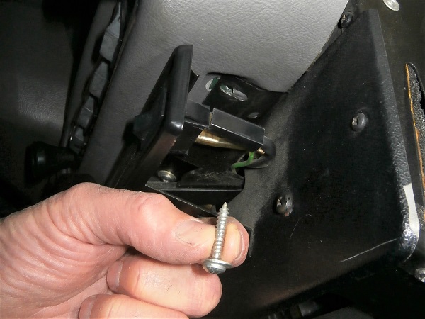
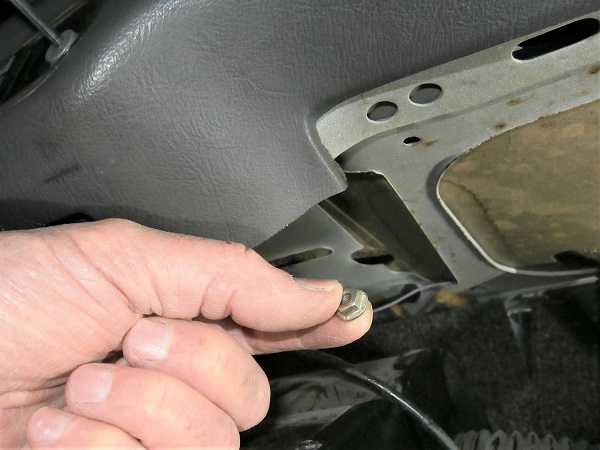
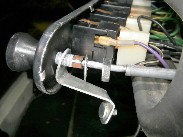
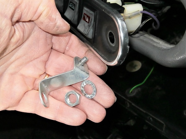
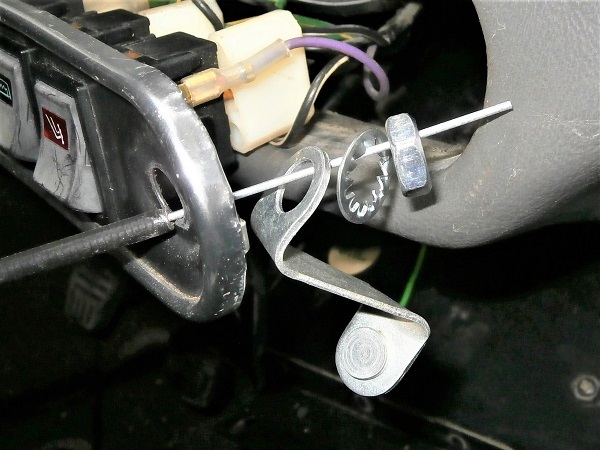
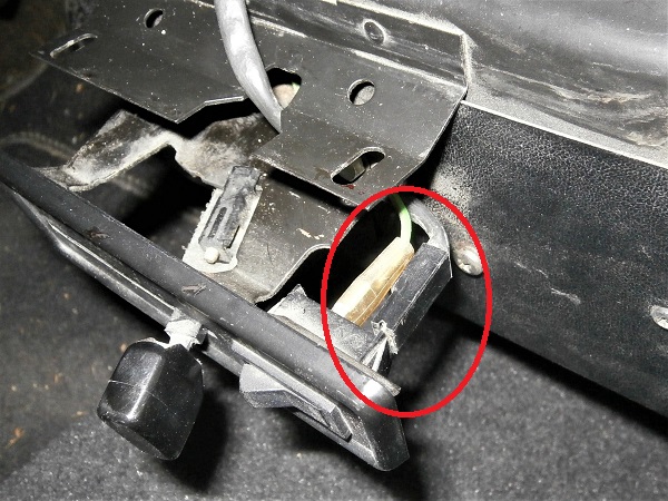
Remove the heater control cable. Pull by hand.
Recover the nut, washer and RH fixing bracket (3rd photo).
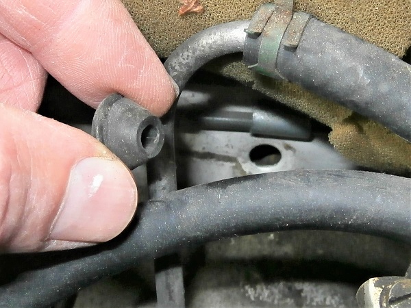
Op 15
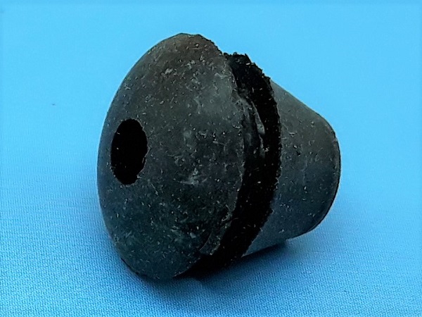
Remove the cable grommet. Pull by hand or use a flathead screwdriver.
The cable grommet is removed towards the front of the bulkhead (engine compartment).
Advertisement
Fit the heater control cable
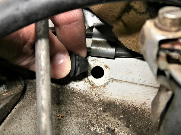
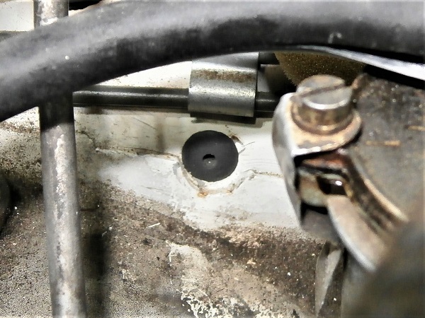
Op 16
Fit the new cable grommet (CAM5969). Use a small flathead screwdriver.
Op 17
Pass the heater control cable (CHM373) through the switch panel as well as the RH fixing bracket, the star washer (GHF323), the nut (GFK3213) and the bulkhead.
Passing the cable through the bulkhead is not an easy operation because it happens under the dashboard so difficult to access and you have to force the cable housing so that it fits into the cable grommet.
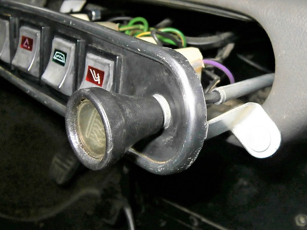
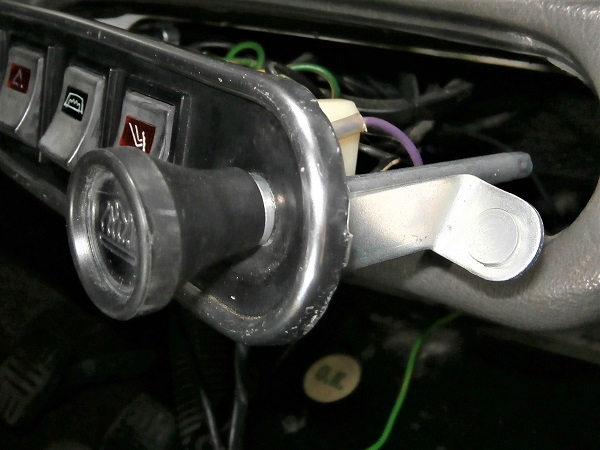
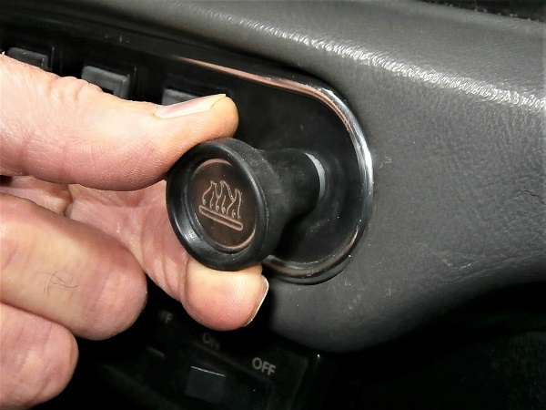
Op 18
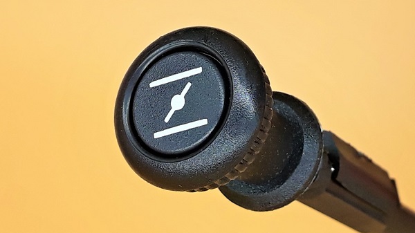
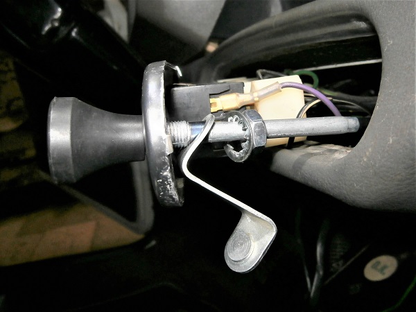
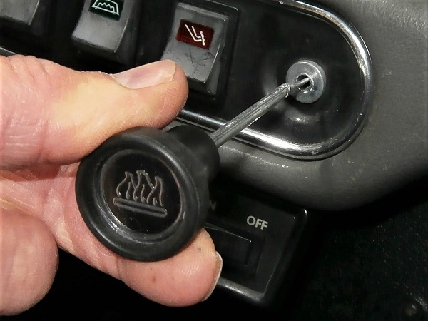
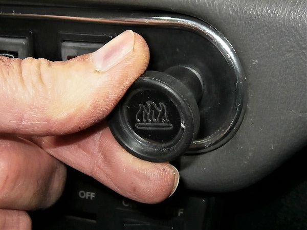
Fit the heater control on the switch panel and tighten the nut. Use the 14 mm spanner.
Place the cable housing in the correct angular position so that the logo on the heater control is horizontal.
Op 19
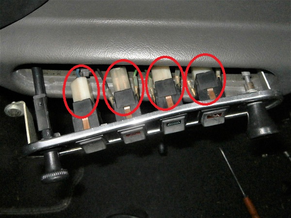
Make sure that all the connectors are properly connected to the switches before positioning the switch panel.
It often happens that the connectors come loose during handling.
Op 20
Engage the switch panel. Push by hand.
Op 21
Place the screws of the 2 fixing brackets in their housings.
Screw the switch panel fixing nuts. Use the 8 mm socket spanner.
Op 22
Connect the electrical wire to the heater fan switch.
Op 23
Lift the heater unit in its normal position.
Screw its 2 fixing screws of the heater unit (with their washers). Use the Phillips screwdriver.
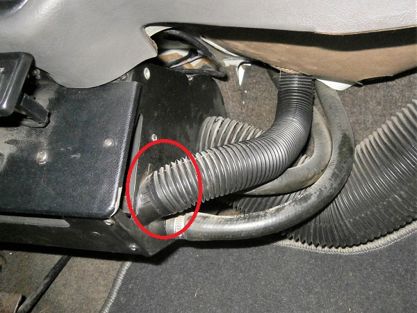
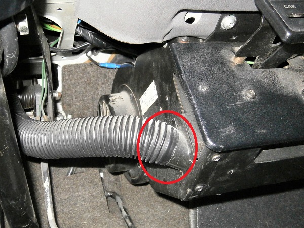
Op 24
Make sure that the heater ducts are still properly fitted on the heater unit.
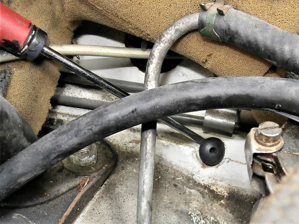
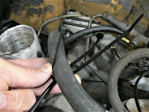
Op 25
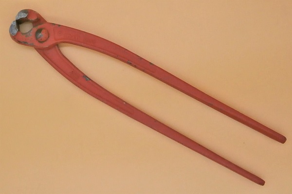
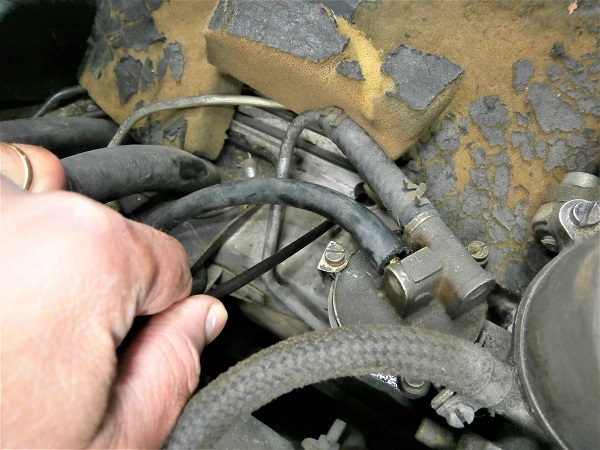
Attach a cable tie to secure the heater control cable to the heater hose. Use the cutting pliers.
Thus the cable will not be in contact with the rocker cover or the exhaust manifold. This will prevent burning the cable housing.
Tighten the cable tie moderately by hand. Do not deform the hose.
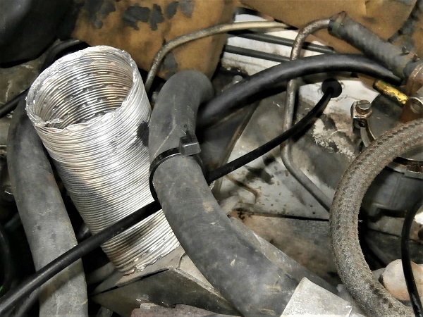
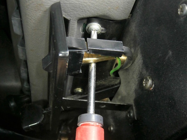
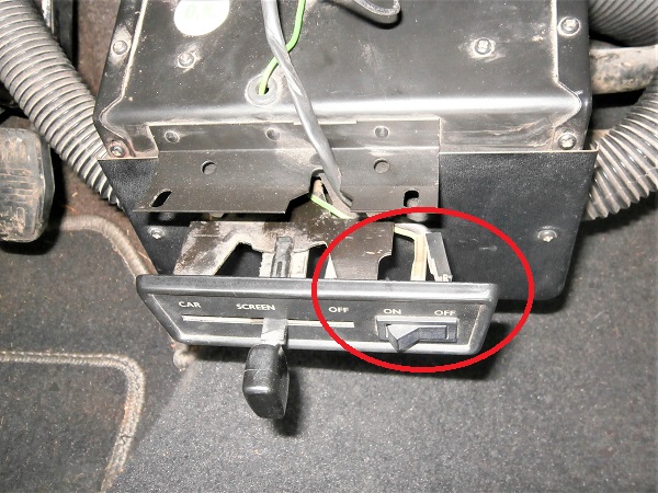
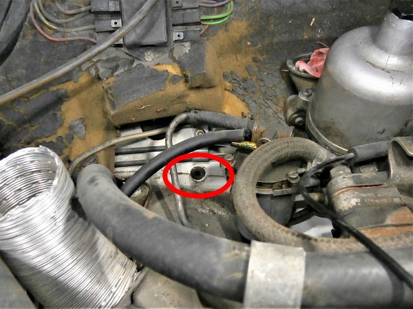
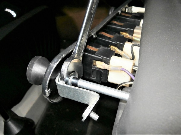
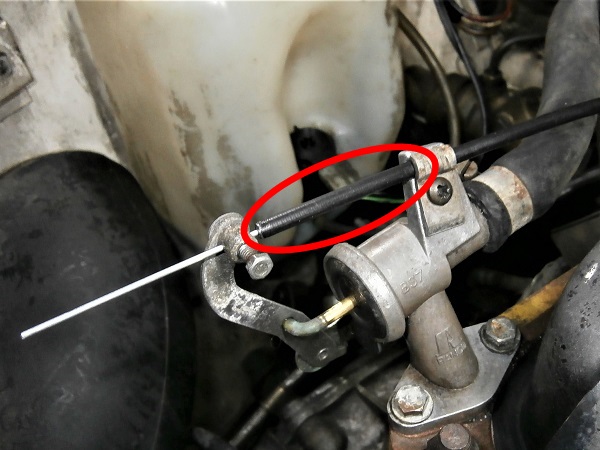
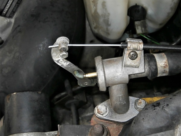
Op 26
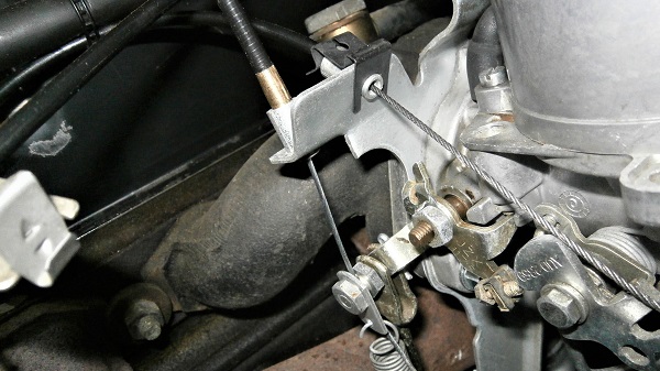
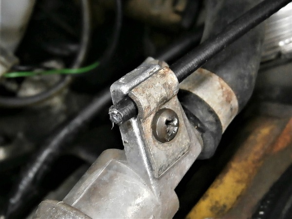
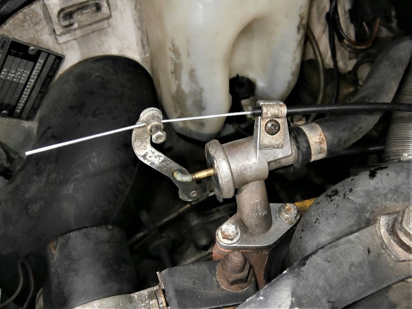
Fit the cable in the cable clamp and the housing in the cable support bracket.
Tighten the cable support bracket. Use the Phillips screwdriver.
Yes. I saw it too. The housing is too long (3rd photo). We're going to shorten it.
Do not lock the cable clamp for the time being.
Op 27
Pull the heater control cable towards the passenger compartment.
Pull a good length to be sure not to cut the cable when you cut the housing.
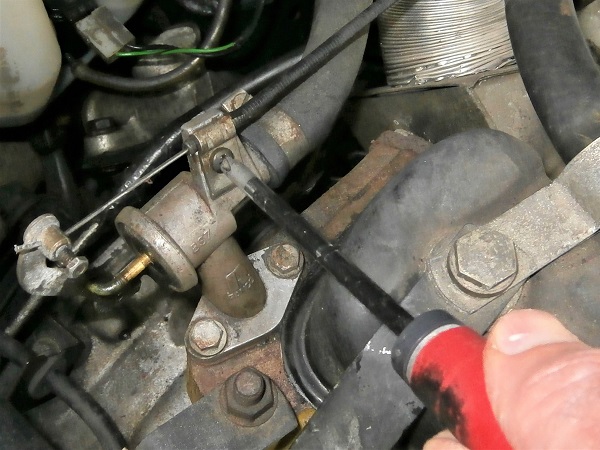
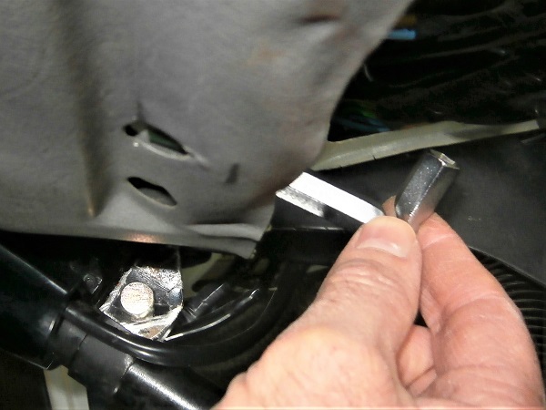
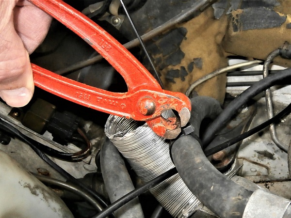
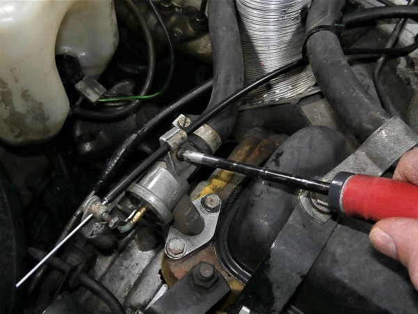
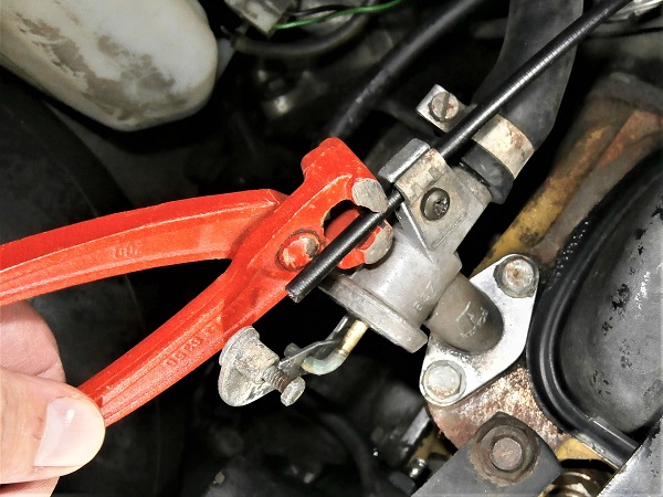
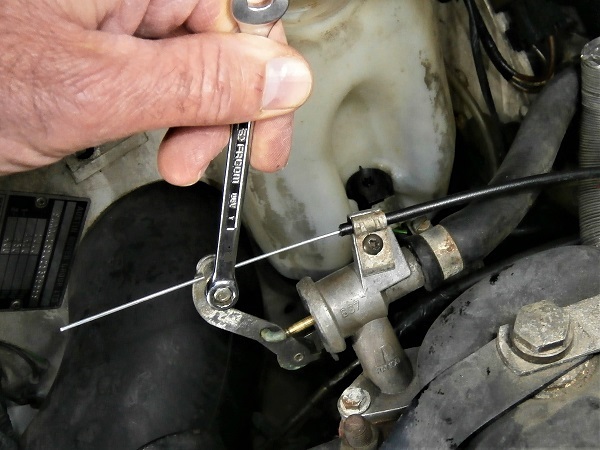
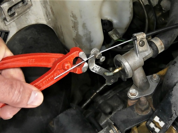
Op 28
Cut the housing at the cable support bracket. Use the cutting pliers.
Fit the jaws of the pliers parallel to the coils of the housing spring. The cut will be much better.
Check carefully that there are no deformations or burrs that could hinder the passage of the cable.
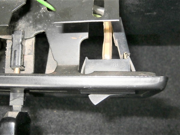
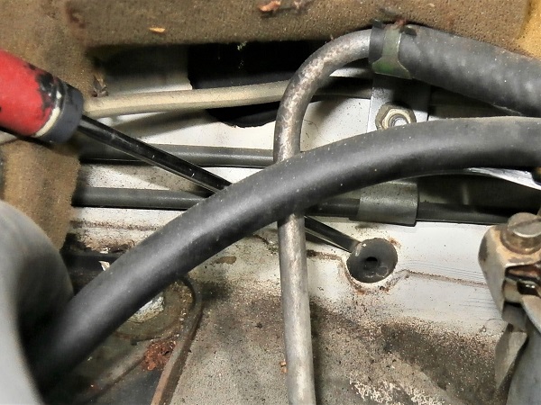
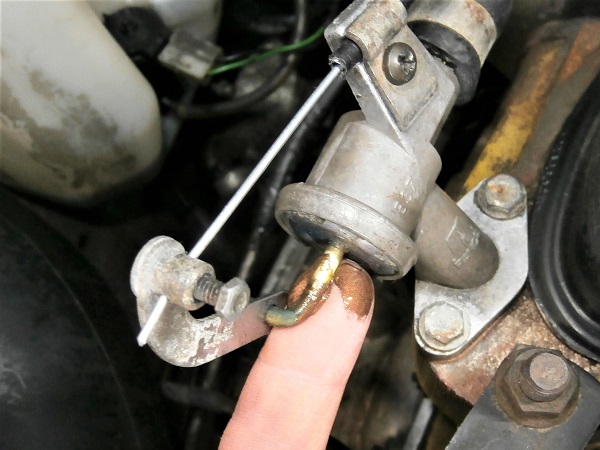
Op 29
Push back the heater control cable.
Make sure the cable passes through the cable clamp again (3rd photo).
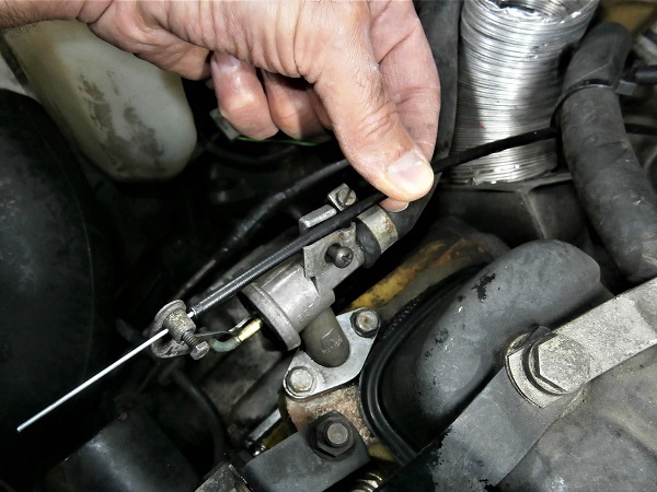
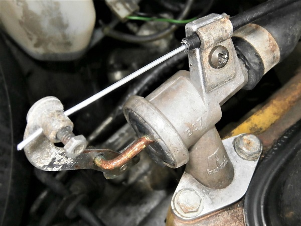
Op 30
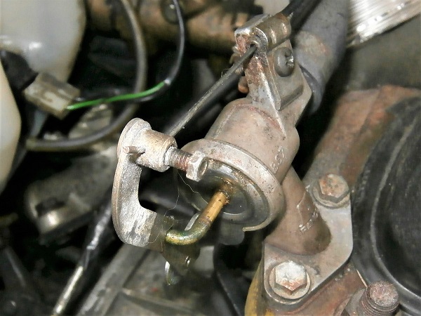
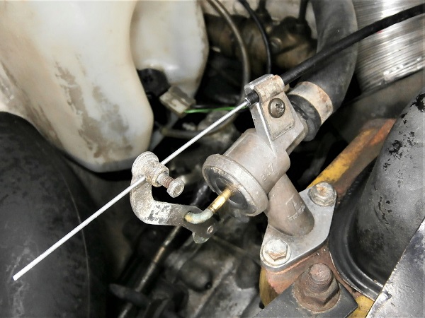
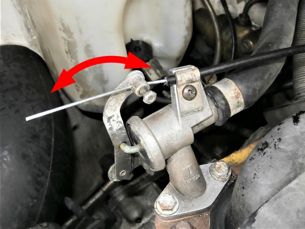
Fit the heater valve lever at maximum extension.
Tighten the cable clamp bolt. Use a 1/4'' spanner.
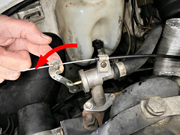
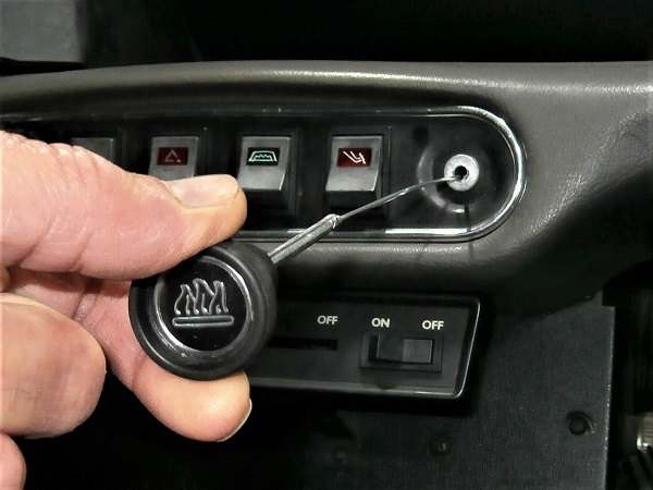
Op 31
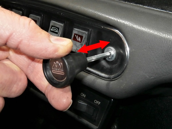
Check that the heater control allows the valve lever to be actuated over its full range.
Op 32
Cut off the end of the cable that protrudes from the lever. Use the cutting pliers.
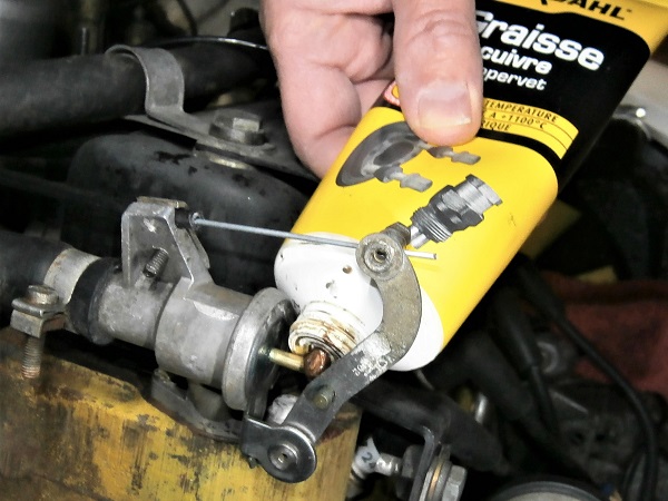
Op 33
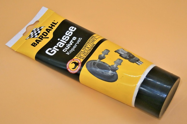
Lightly grease the heater valve shaft. Use copper grease.
The heater control will be smoother to operate and the heater valve will last a few more years.
Op 34
Fit the air filter box (➔ see the tutorial ''Changing the HS4 air filter'' Op 10 to 13).
The End