
This tutorial is also available in French
➔

Steering rack gaiters change on Austin Mini
Vehicle ➔ Mini 1000 year 1988
Difficulty ➔ Easy
Time ➔ 1 hour
Summary
Advertisement
Advertisement

Recommendations

A torn steering rack gaiter must be changed without delay. Indeed, the gaiter protects the rack against any intrusion of dust or other projections. If you delay replacing the gaiter, you will have to change the rack.

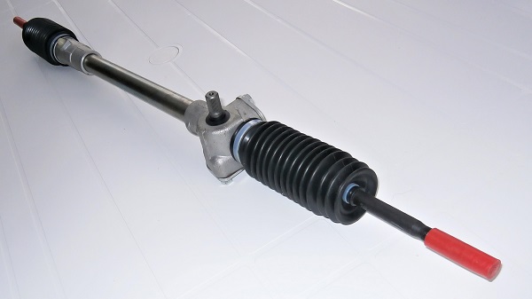
There are several different rack gaiter kits available :
• BHM7113 : 2 identical gaiters. Length 4.5'' (11.4 cm).
• GSV1004 : 2 different gaiters. Lengths 6.5'' and 6.75'' (16.5 cm and 17 cm). Diameters on the rack side 42.4 mm and 26.7 mm.
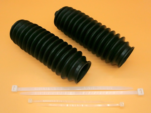
• GSV1056 : 2 identical gaiters. Length 7.5'' (19 cm).
Be sure to check which gaiters are fitted to your Mini before ordering.
• BHM7113 : 2 identical gaiters. Length 4.5'' (11.4 cm).
• GSV1004 : 2 different gaiters. Lengths 6.5'' and 6.75'' (16.5 cm and 17 cm). Diameters on the rack side 42.4 mm and 26.7 mm.
• GSV1056 : 2 identical gaiters. Length 7.5'' (19 cm).
Be sure to check which gaiters are fitted to your Mini before ordering.
When you unscrew a track rod end from the steering rack, be sure to count the number of turns. This will allow you to reinstall the track rod end more accurately. Nevertheless, this will not exempt you from having the alignment adjusted afterwards.
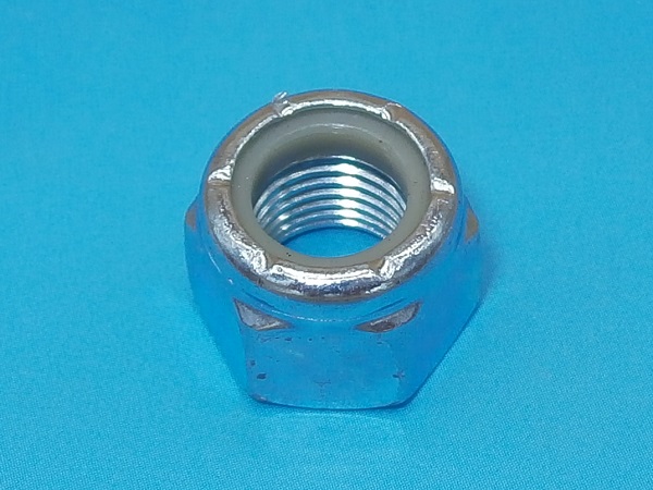
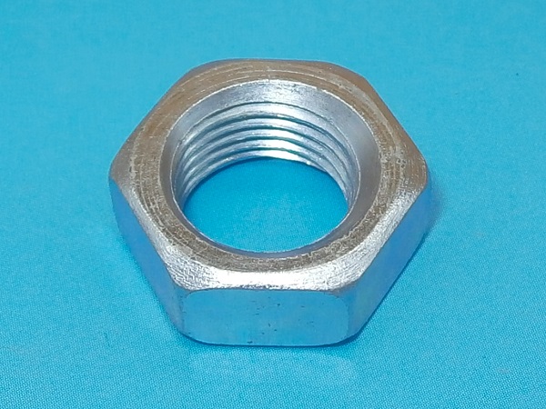
The track rod end fixing nuts (GFK3323) are nyloc nuts. Before reassembling such a nut, check that the nylon ring is in good condition and guarantees braking. If in doubt, as a safety measure, fit a new nut.
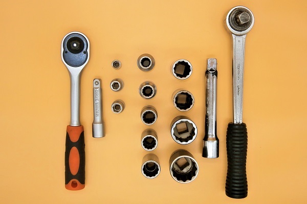
Required Tools
Sponsored links by

Spare Parts
Our Partners


Packaging :
•
GSV1056 : The kit includes 2 rack gaiters + 4 cable ties.
• The other parts above are sold individually.
• The other parts above are sold individually.
Advertisement
Remove the track rod end
Op 01
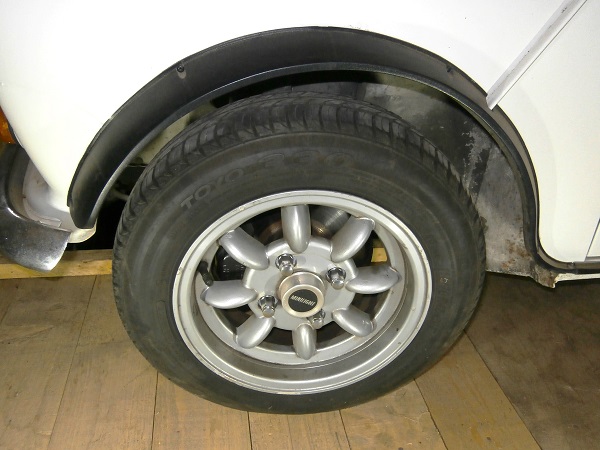
Lift the wheel :
•
Apply the handbrake.
•
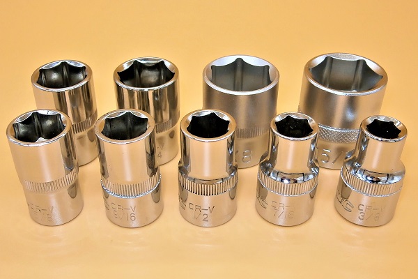
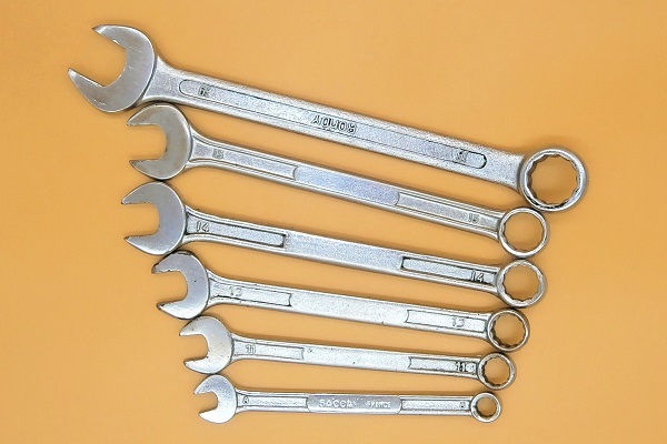
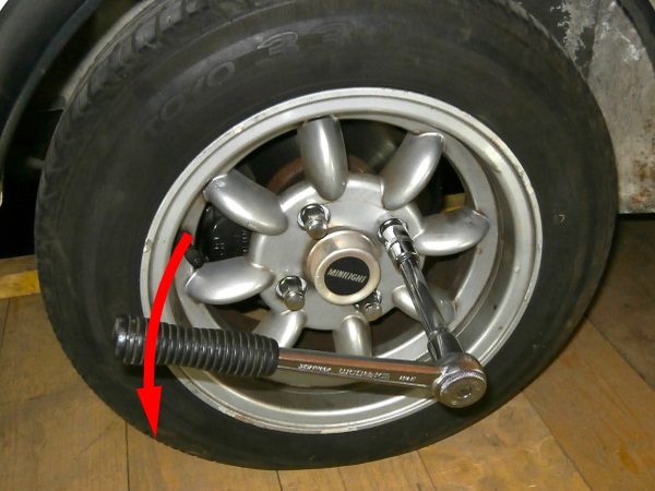
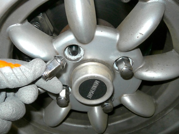
Slightly loosen the 4 wheel nuts. Use the 11/16'' socket.
•
Lift the wheel. Use the jack.
•
Fit jack stands or rigid chocks to guarantee your safety.
Before working under the vehicle, make sure to secure it properly with jack stands or rigid chocks. Never work under a vehicle supported only by a jack. It is too dangerous.
Op 02
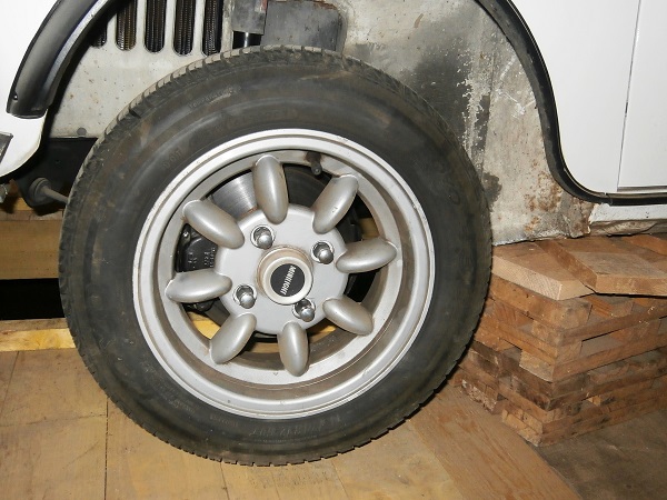
Remove the wheel :
•
Remove the 4 wheel nuts. Unscrew by hand.
•
Remove the wheel. Pull by hand.
Op 03
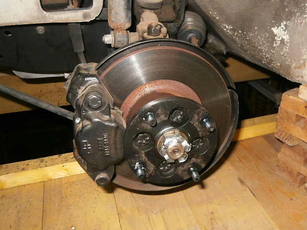
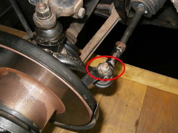
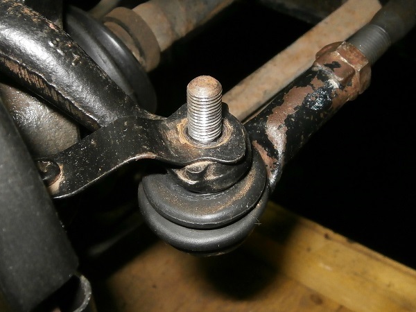
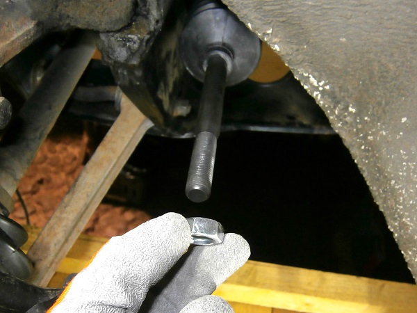
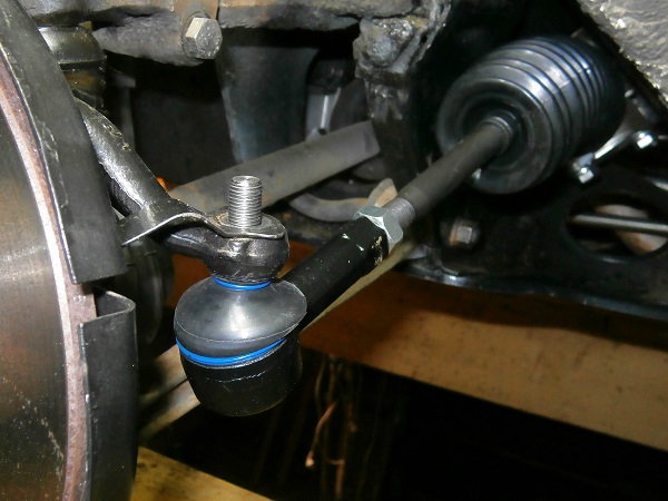
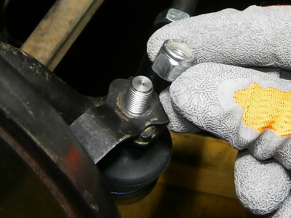
Remove the track rod end fixing nut. Use the 9/16'' socket.
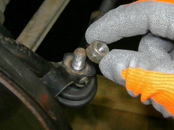
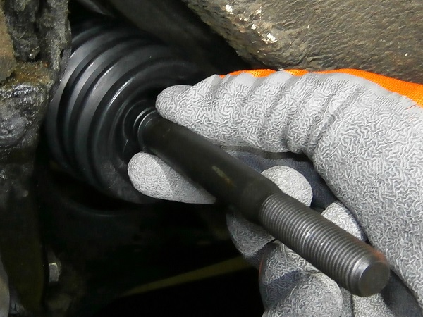
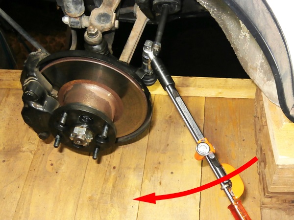
Op 04
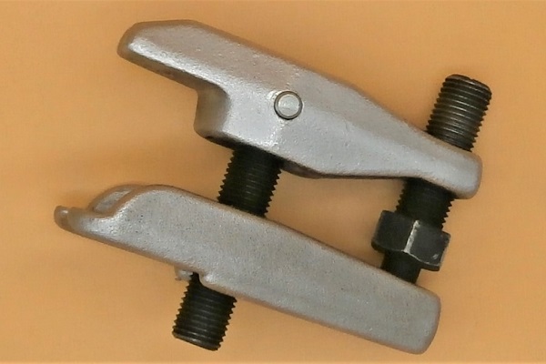
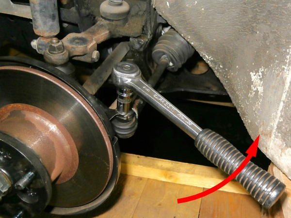
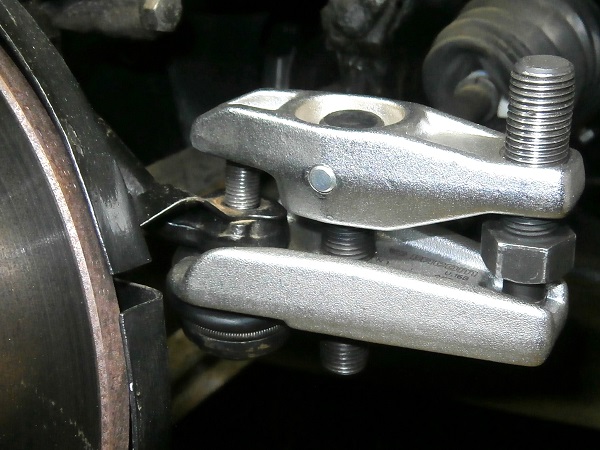
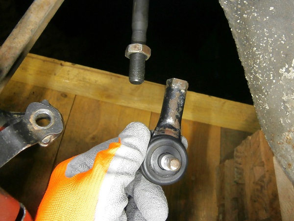
Pull off the track rod end from the steering arm. Use the ball joint puller.
Be careful not to tear the track rod end gaiter when installing the ball joint puller.
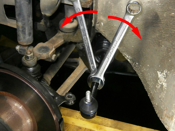
Op 05
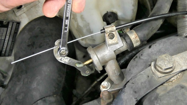
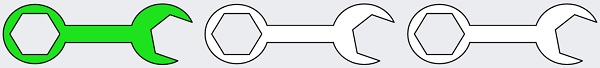
Loosen the track rod end half lock nut. Use the two 19 mm spanners.
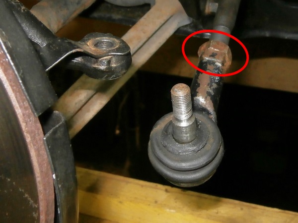
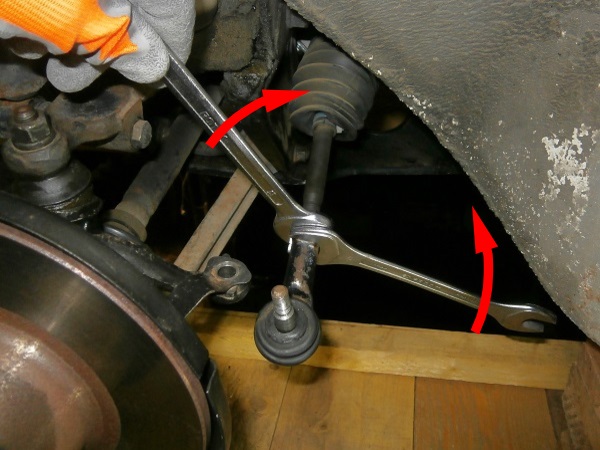
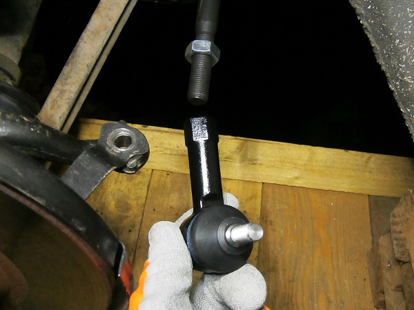
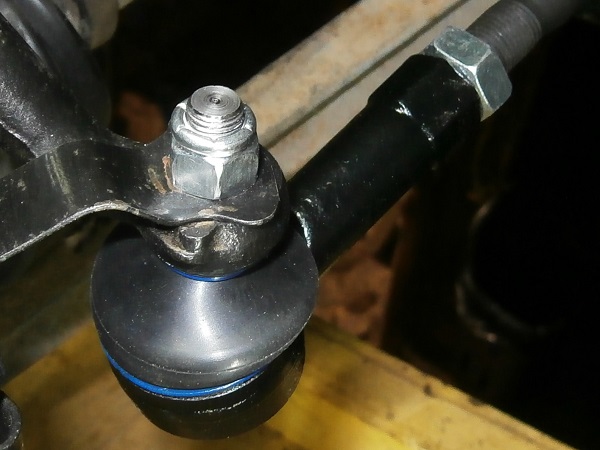
Op 06
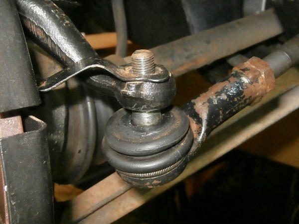
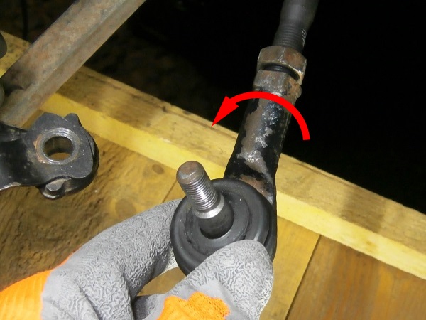
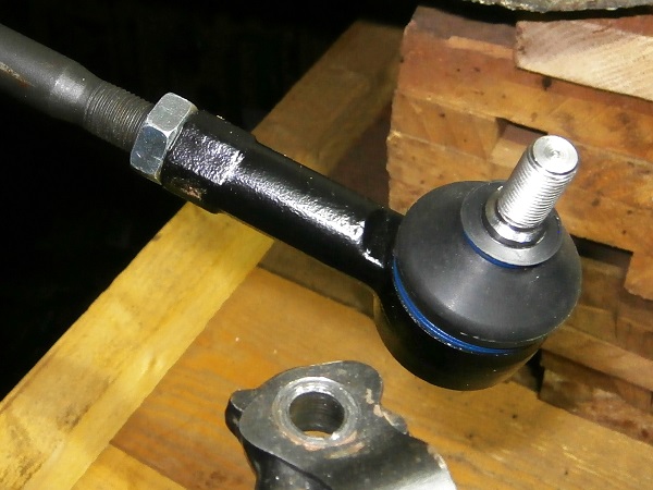
Remove the track rod end. Unscrew by hand.
Count the number of turns when unscrewing the track rod end. This will allow it to be positioned approximately during reassembly.
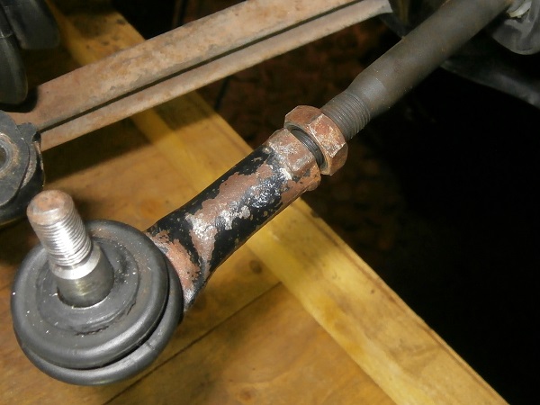
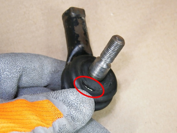
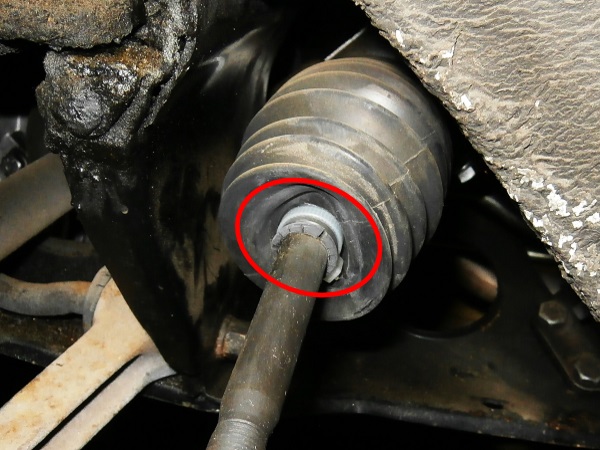
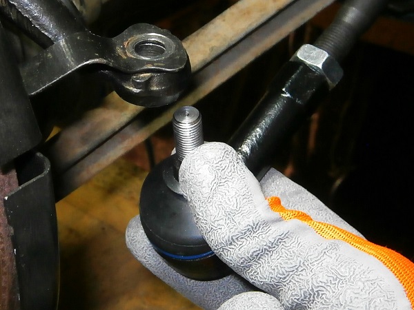
Check that the track rod end gaiter is in perfect condition. If the gaiter is torn (3rd photo), it will need to be changed (or the track rod end changed).
Op 07
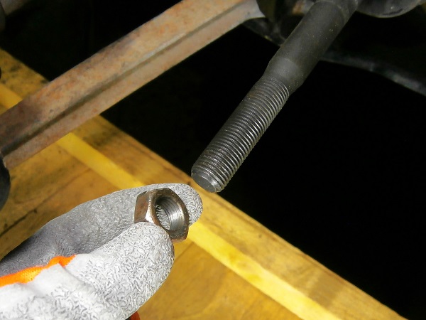
Remove the track rod end half lock nut. Unscrew by hand.
Advertisement
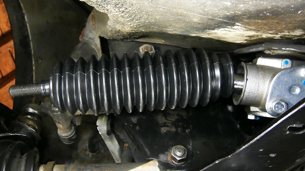
Remove the steering rack gaiter
Op 08
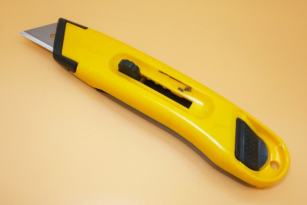
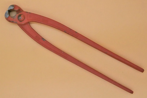
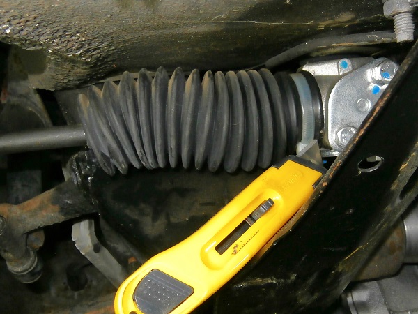
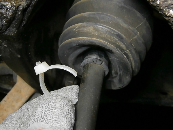
Cut the gaiter retaining tie on the rack side. Use a cutter.
Remove the retaining tie.
Op 09
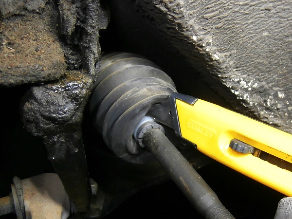
Cut the gaiter retaining tie on the track rod end side. Use a cutter.
Remove the retaining tie.
Op 10
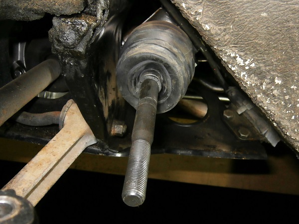
Remove the rack gaiter. Pull by hand.
Fit the steering rack gaiter
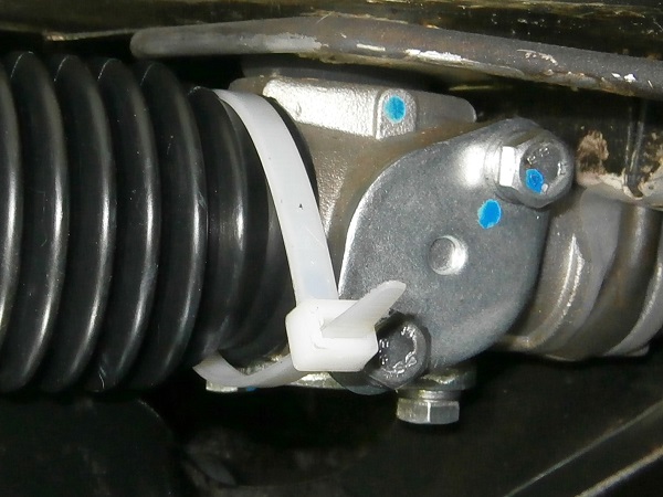
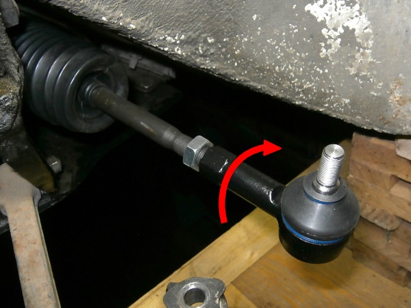
Op 11
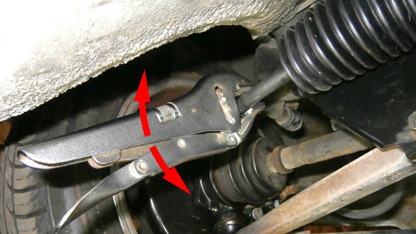
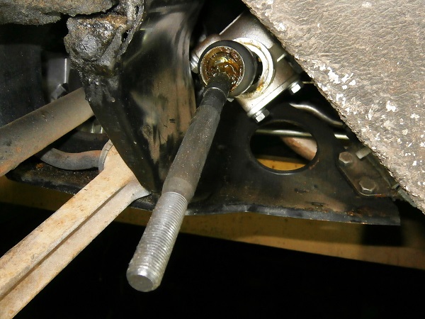
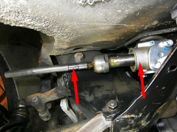
Mark where the new gaiter should be positioned (see the 2 arrows in the photo) :
•
On the rack body.
•
In the steering rod groove.
Op 12
Fit the new gaiter (GSV1056 kit) :
•
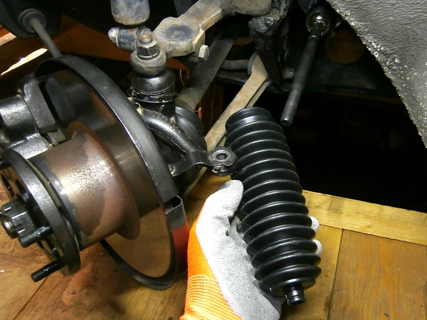
Engage the gaiter on the steering rod. Push by hand.
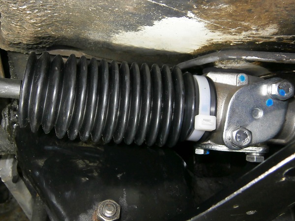
•
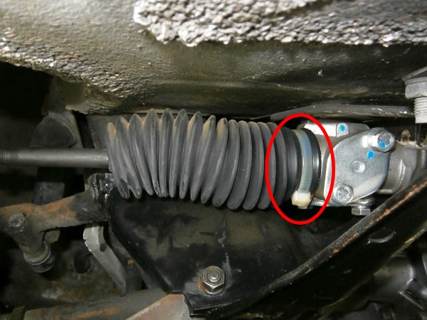
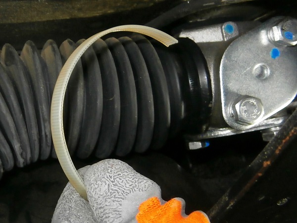
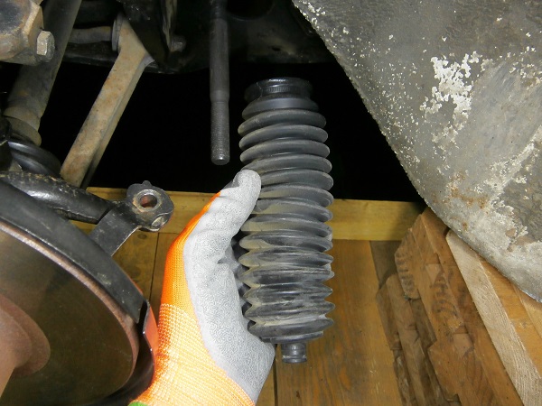
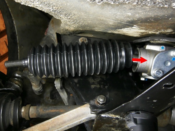
Fit the gaiter on the body of the steering rack (3rd photo). Pull the gaiter by hand and if necessary use a piece of bent wire.
•
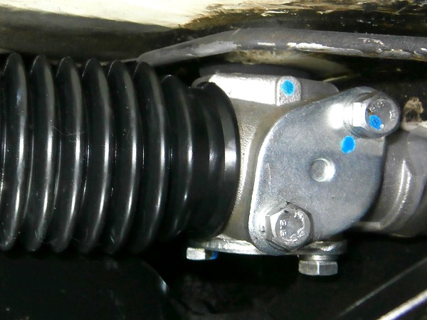
Fit the other end of the gaiter in the groove of the steering rod (4th photo). Push by hand.
Positioning the gaiter on the rack is not really easy to do. There is not much room and the gaiter is not very flexible. I succeeded by using a piece of wire with a bent end.
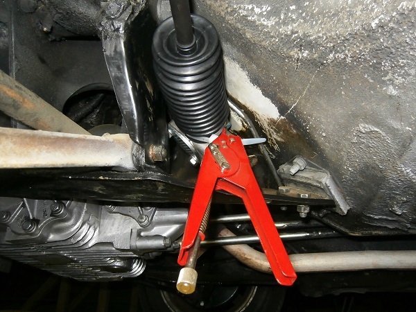
Op 13
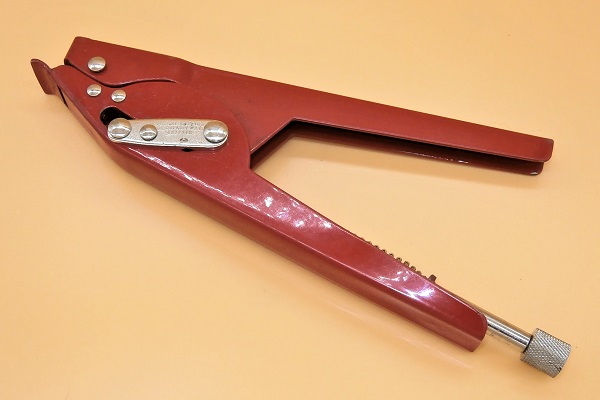
Fit the gaiter retaining tie on the rack side.
Tighten the tie moderately. Use the cable tie pliers.
Cut off the end of the tie that sticks out. Use the cutting pliers.
Do not tighten the tie too tight as this could damage the gaiter.
There is no need to position the tie on the track rod end side for the moment. When adjusting the alignment, the steering rod must be able to rotate without moving the gaiter.
Advertisement
Fit the track rod end
Op 14
Fit the track rod end half lock nut (NT608041) on the steering rack. Screw by hand.
Fit the track rod end on the steering rack. Screw by hand.
Screw the track rod end the same number of turns as during disassembly. This allows a first approach to the alignment of the front wheels.
Op 15
Firmly tighten the half lock nut against the track rod end. Use the two 19 mm spanners.
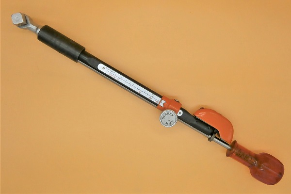
The tightening torque of the track rod end half lock nut is 52 mN. This operation requires a specific torque wrench with an open-end spanner. If, like me, you don't have this type of wrench, tighten it firmly.
Op 16
Fit the axis of the track rod end in the steering arm.
Op 17
Screw on the track rod end nut (GFK3323). Use the 9/16'' socket.
Tighten the nut to a torque of 30 mN. Use the torque wrench.
Op 18
Fit the wheel :
•
Fit the wheel on the drive flange.
•
Screw on the 4 nuts. Use the 11/16'' socket.
•
Lower the Mini to the ground. Remove the jack stands.
•
Tighten the 4 nuts to the torque corresponding to the type of rim. Use the torque wrench.
The tightening torque of the wheel nuts is :
• 63 mN for steel rims.
• 50 mN for alloy rims.
• 63 mN for steel rims.
• 50 mN for alloy rims.
Change the 2nd steering rack gaiter
Op 19
Change the 2nd steering rack gaiter. Proceed in the same way.
Have the front wheel alignment
Op 15
Have the front wheel alignment adjusted.
The End