This tutorial is also available in French
➔

Replacing the front shock absorbers and strut upper mounts on Twingo 2

Vehicle ➔ Twingo 2 1.2 16v year 2009
Difficulty ➔ Medium

Time ➔ 3 hours
Summary
Advertisement
Advertisement

Recommendations

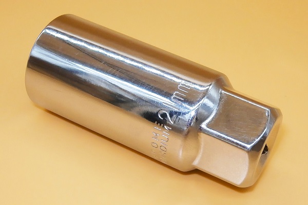
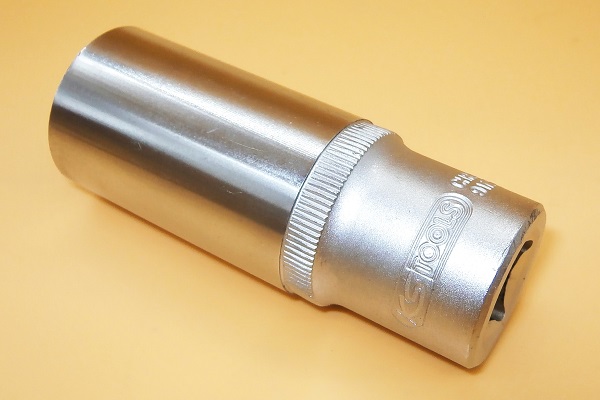
When disassembling the strut upper mount, you will have to unscrew the nut which is slightly recessed in the strut upper mount countersink while immobilizing the shock rod in rotation. The best way to carry out this operation is to use a 21 mm go-through socket.
This socket :
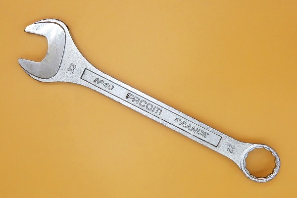
• Can be operated by its periphery using a 22 mm spanner, which allows unscrewing the nut.
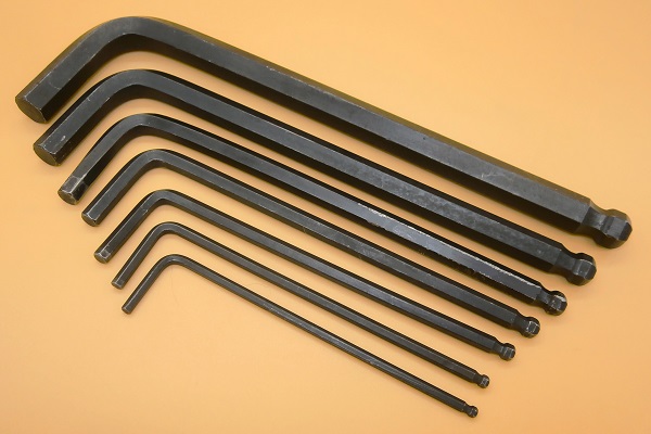
• Allows the passage of the 6 mm allen key in its axis, which makes it possible to immobilize the shock rod.
This socket :
• Can be operated by its periphery using a 22 mm spanner, which allows unscrewing the nut.
• Allows the passage of the 6 mm allen key in its axis, which makes it possible to immobilize the shock rod.
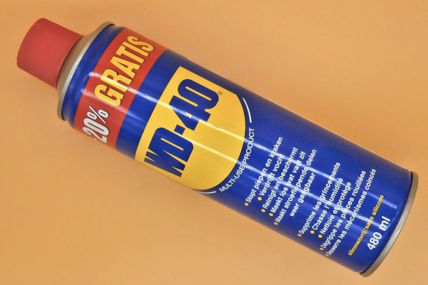
The lower strut mounting bolts and nuts are frequently oxidized. Do not hesitate to coat them with penetrating oil before unscrewing them.

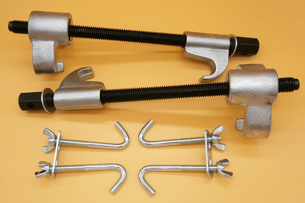
Compressing the coil spring is a very delicate and dangerous operation. Always use a good quality coil spring compressor suitable for Twingo shock absorbers.
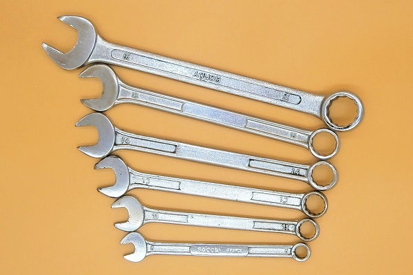
Required Tools
Sponsored links by


Spare Parts
Sponsored links by


Packaging :
•
7700829529 : The front suspension strut upper mount kit includes 2 upper strut nuts, 2 strut upper mounts, 2 shock rod nuts, 2 top strut mounting cushion and 2 bearings.
• 7700819237 : The dust cap kit includes 2 rubber protections.
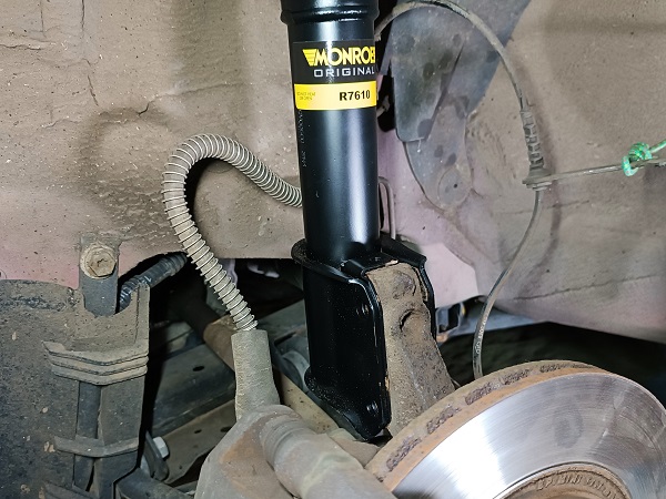
• 8200367895 : The front shock absorbers are sold in pairs or individually (check carefully before ordering). They can be fitted to the front RH side or front LH side of the Twingo.
• 7700819237 : The dust cap kit includes 2 rubber protections.
• 8200367895 : The front shock absorbers are sold in pairs or individually (check carefully before ordering). They can be fitted to the front RH side or front LH side of the Twingo.
Advertisement
Preliminary actions
Op 01
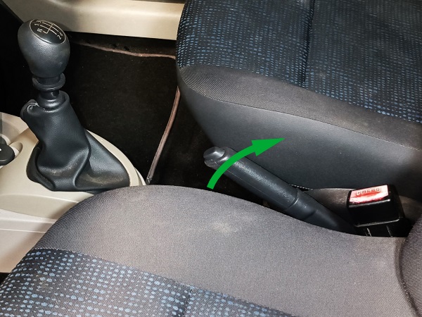
Apply the handbrake.
Op 02
Remove the wiper arms (➔ see the tutorial ''Windscreen trim removal'' Op 01 to 04).
Op 03
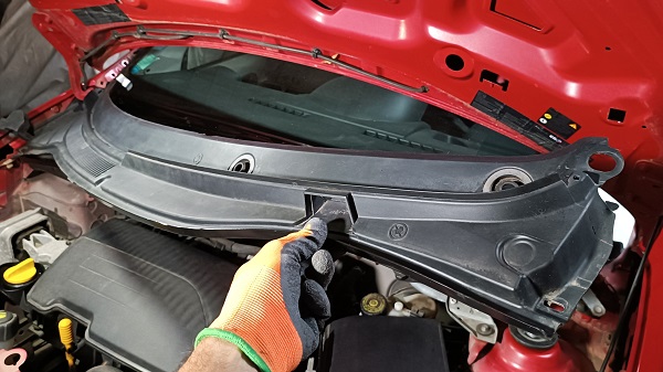
Remove the windscreen trim (➔ see the tutorial ''Windscreen trim removal'' Op 05 to 12).
Op 04
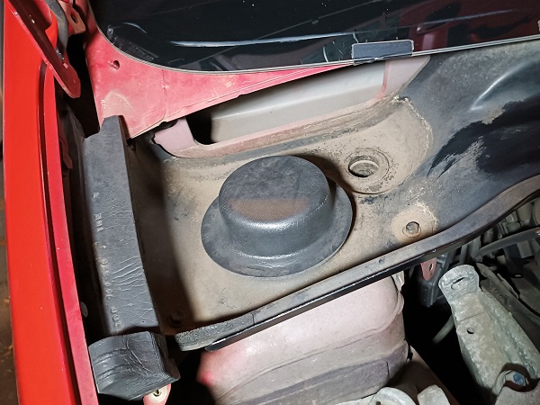
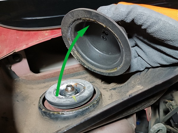
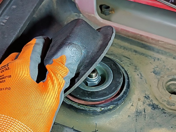
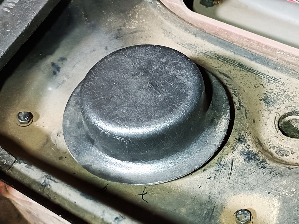
Remove the strut upper mount cover on the RH side. Pull by hand.
The cover is glued to its support. Be very careful. Do not tear it when you remove it.
There is no strut upper mount cover on the LH side.
Remove the LH front strut
Op 05
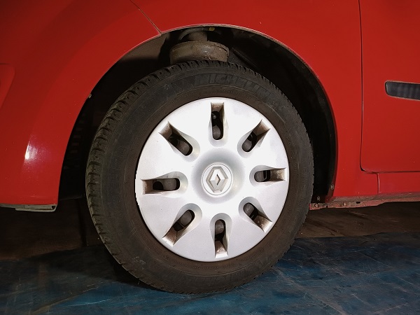
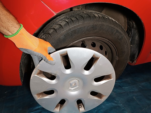
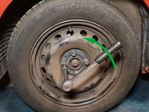
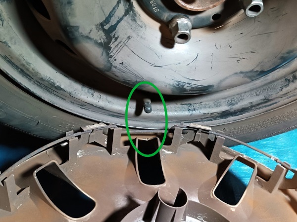
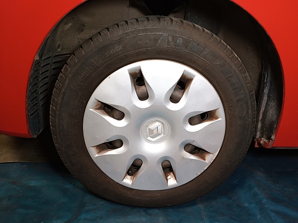
Remove the LH wheel trim. Use the hook supplied with the vehicle.
The hook must be positioned at the valve recess (2nd photo).

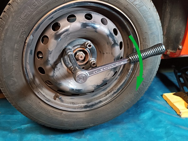
Op 06
Slightly loosen the 4 wheel bolts. Use the 17 mm socket.
Do not remove the bolts for now.

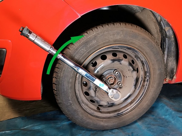
Op 07
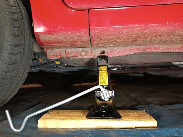
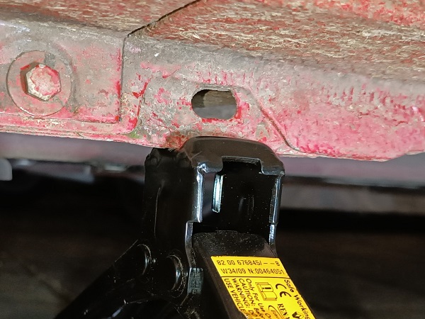
Lift the wheel. Use the jack.
Fit the jack under the vertical sill rib under the oblong hole (2nd photo).
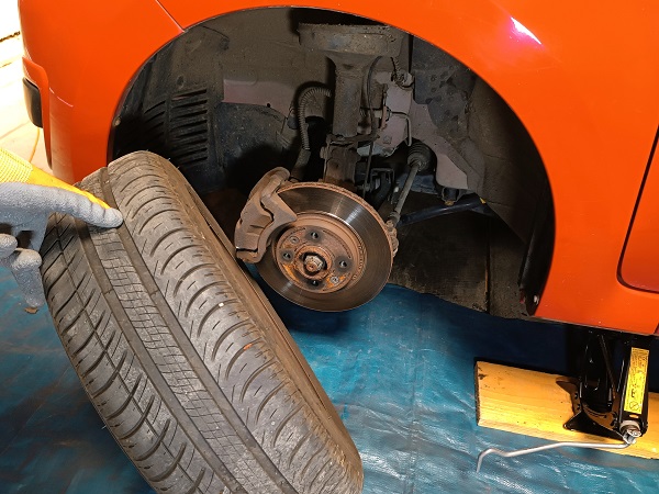
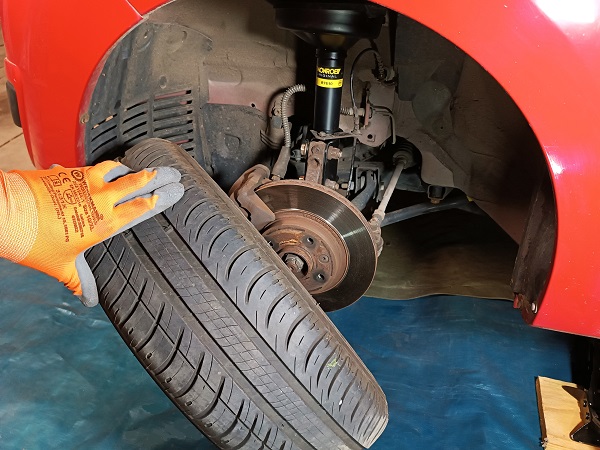
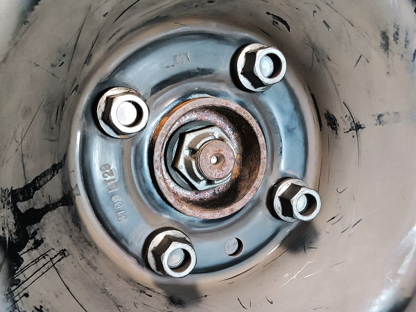
Op 08
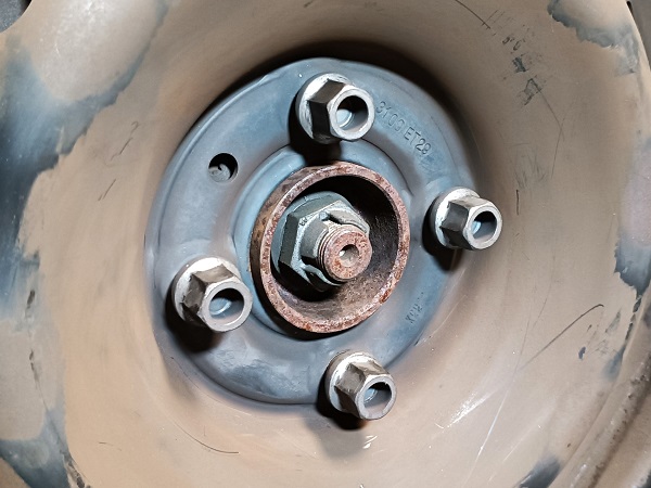
Remove the 4 wheel bolts. Unscrew by hand.
Remove the wheel. Pull by hand.
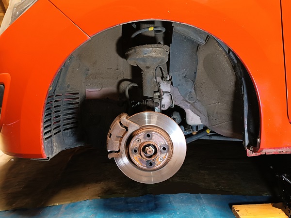
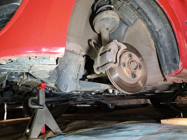
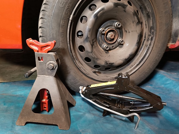
Op 09
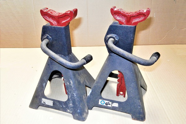
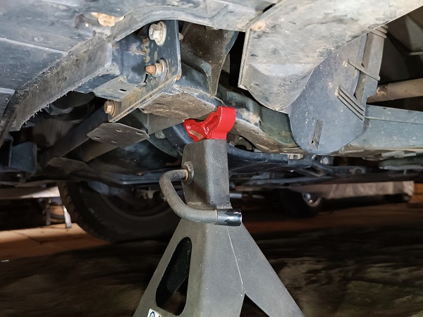
Secure the vehicle. Use a jack stand.
Before working under the vehicle, make sure to secure it properly with jack stands or rigid chocks. Never work under a vehicle supported only by a jack. It is too dangerous.
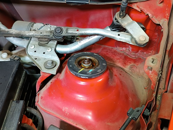
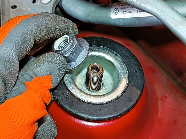
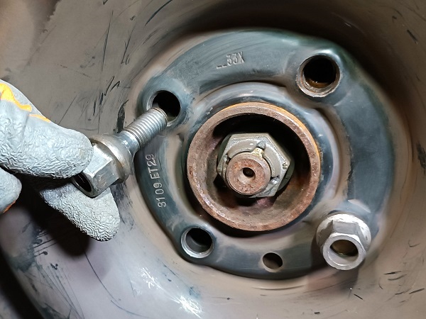
Op 10
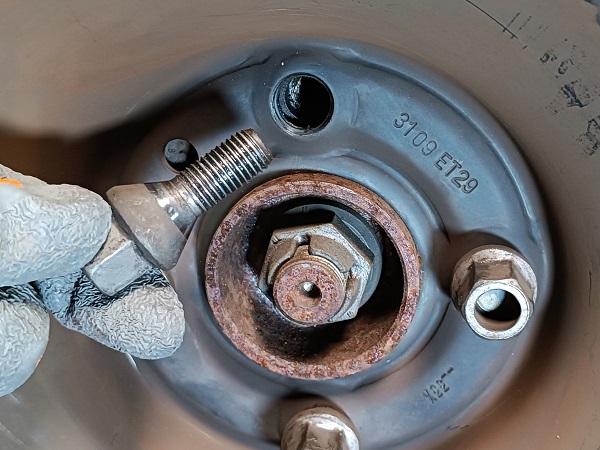
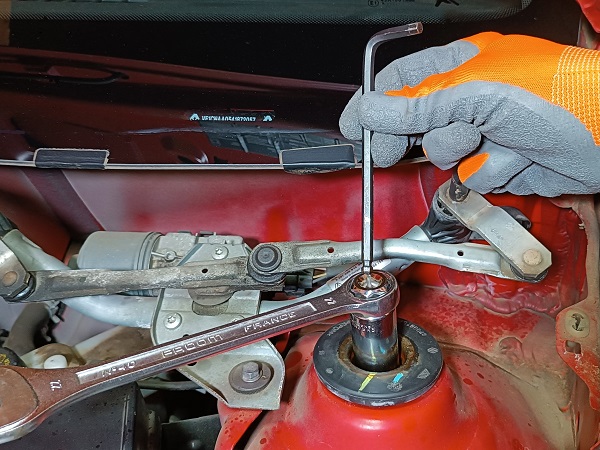
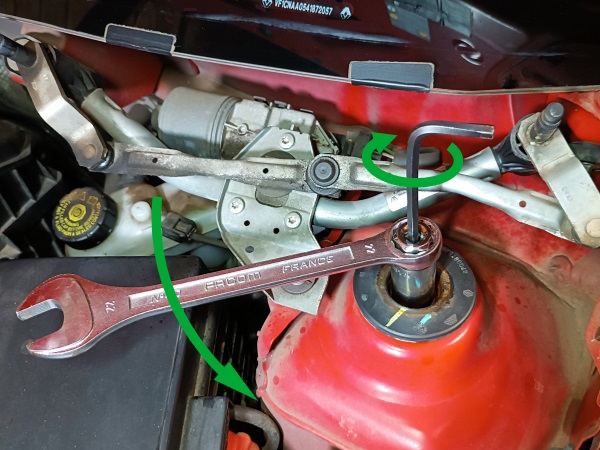
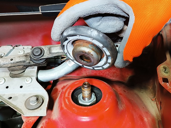
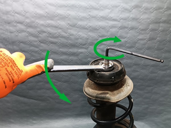
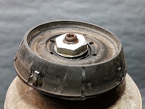
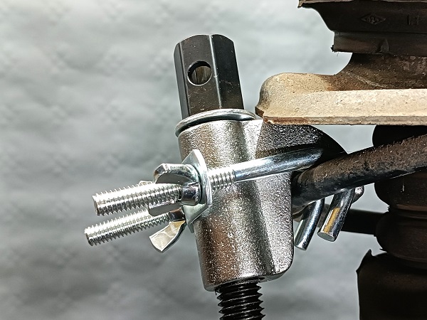
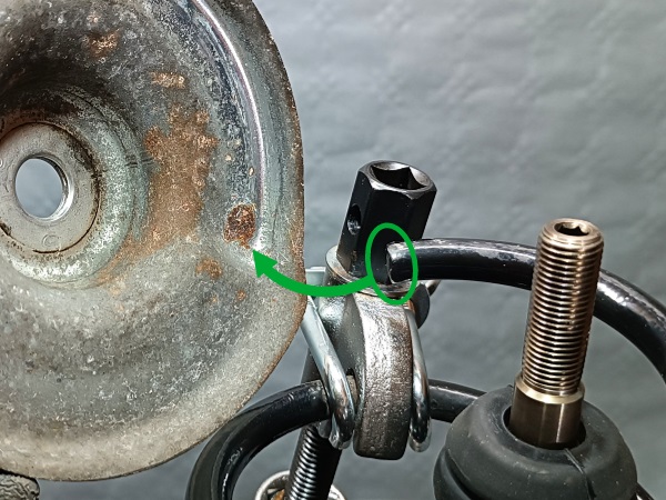
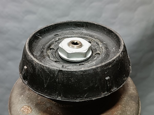
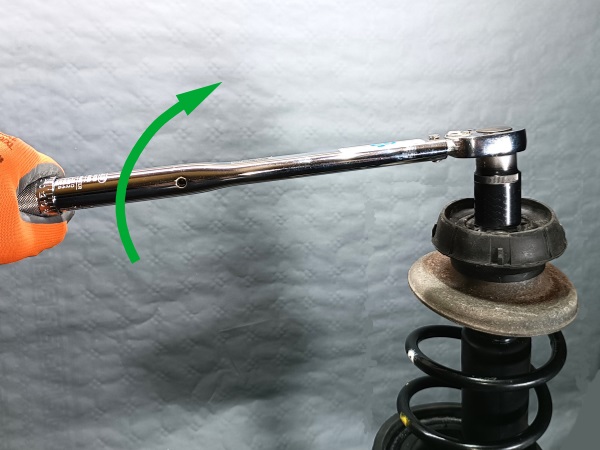
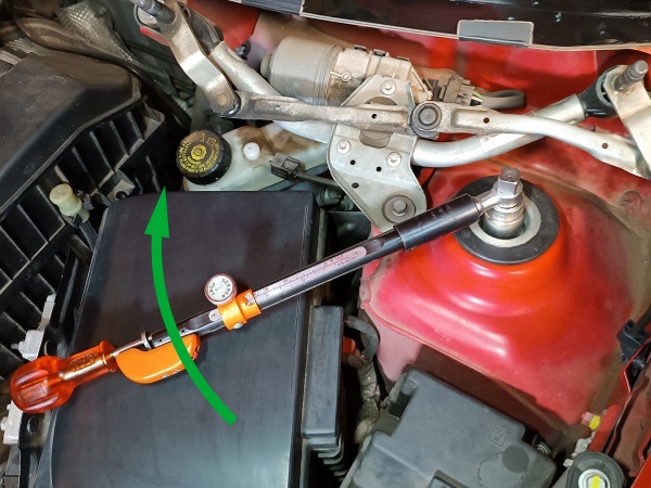
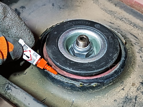
Unscrew the upper strut nut :
•
Fit the 21 mm go-through socket on the nut (2nd photo).
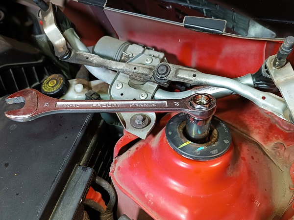
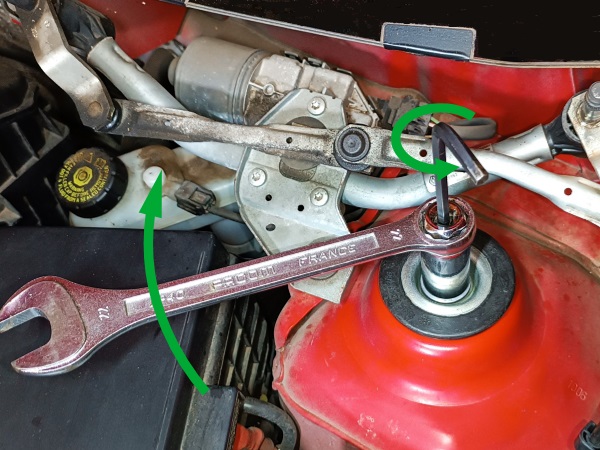
•
Fit the 22 mm spanner on the socket (3rd photo).
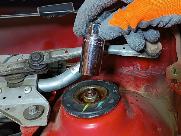
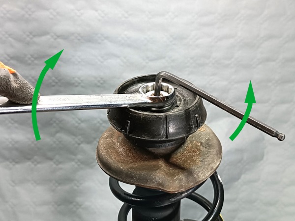
•
Fit the 6 mm allen key through the socket on the shock rod (4th photo).
•
Unscrew the nut (5th photo).
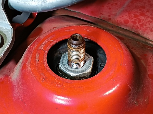
If, as on our Twingo, the shock rod is oxidized, do not hesitate to spray penetrating oil before starting the disassembly.
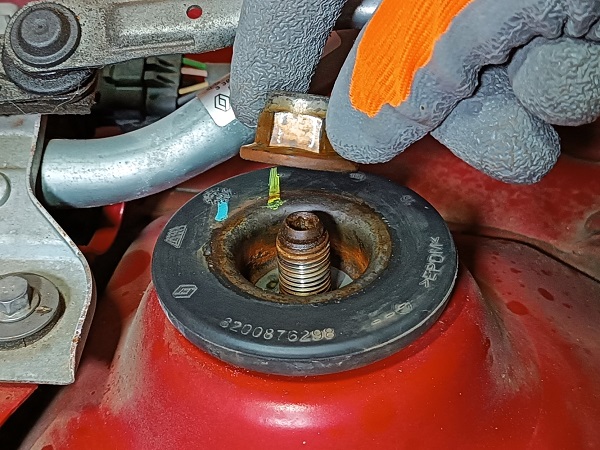
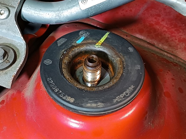
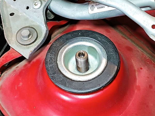
Op 11
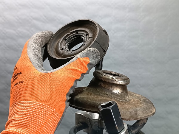
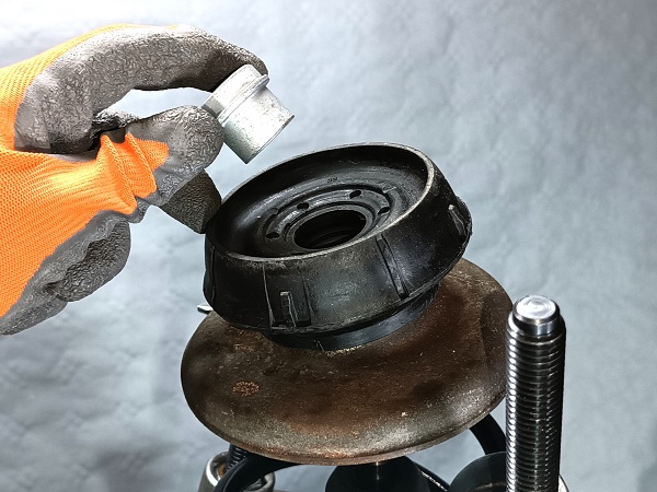
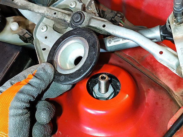
Remove the strut upper mount.
Op 12
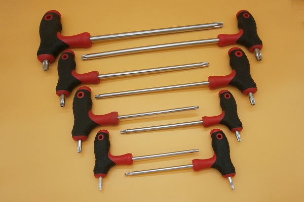
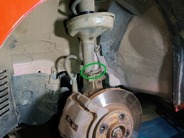
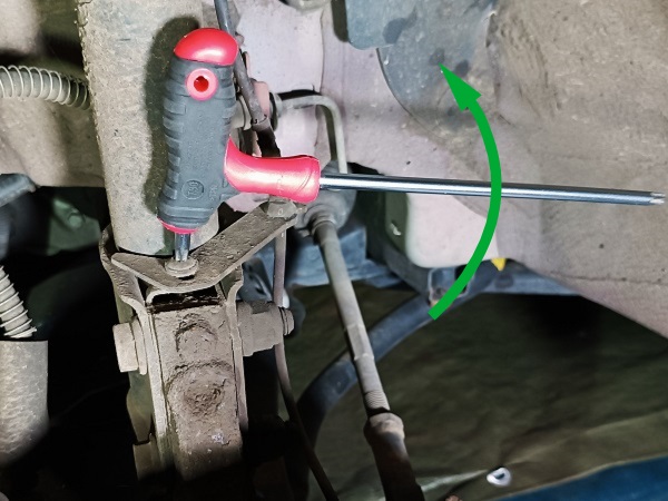
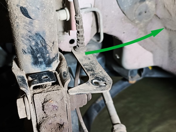
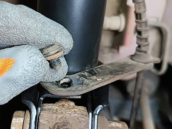
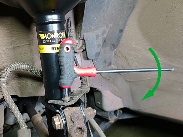
Remove the ABS sensor harness mounting screw. Use the T30 torx key.
Op 13
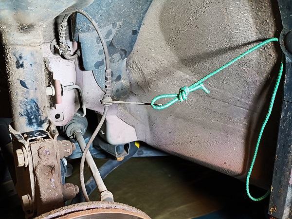
Move the ABS harness away from the work area. Use a string.
Op 14
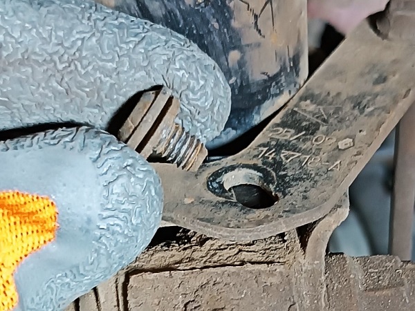
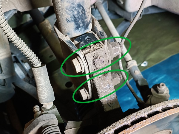
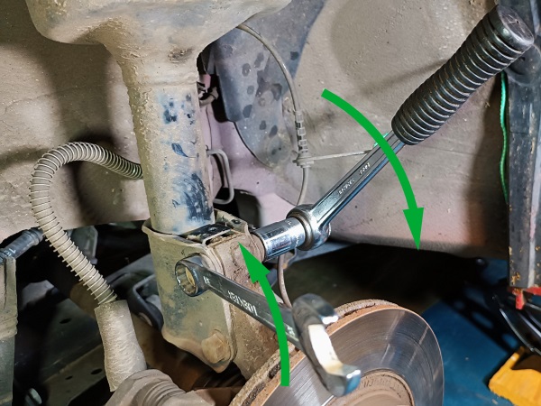
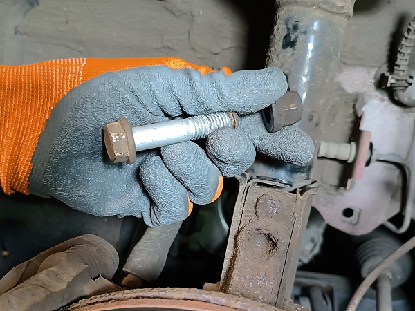
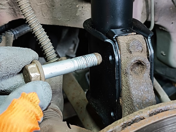
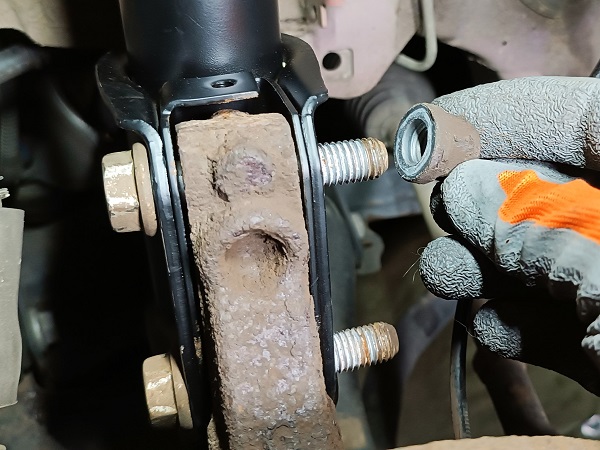
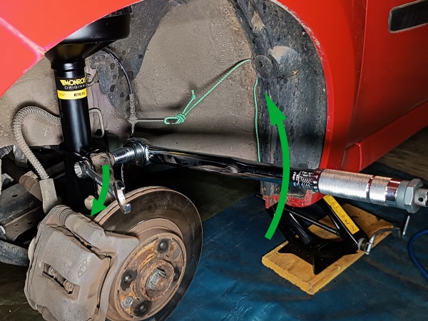
Remove the 2 lower strut mounting bolts and nuts. Use the socket and the 18 mm spanner.
Be sure to secure the strut before removing the last mounting bolt. It is relatively heavy and may damage the driveshaft gaiter if it falls on it.
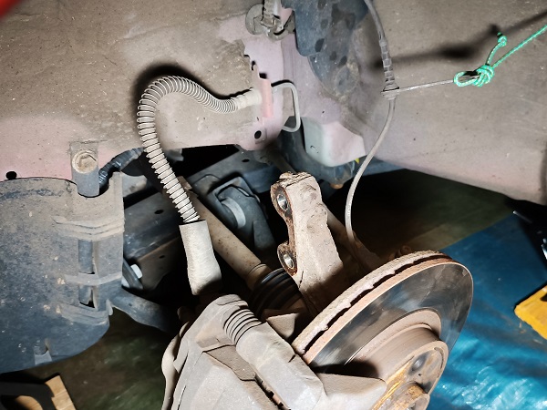
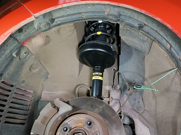
Op 15
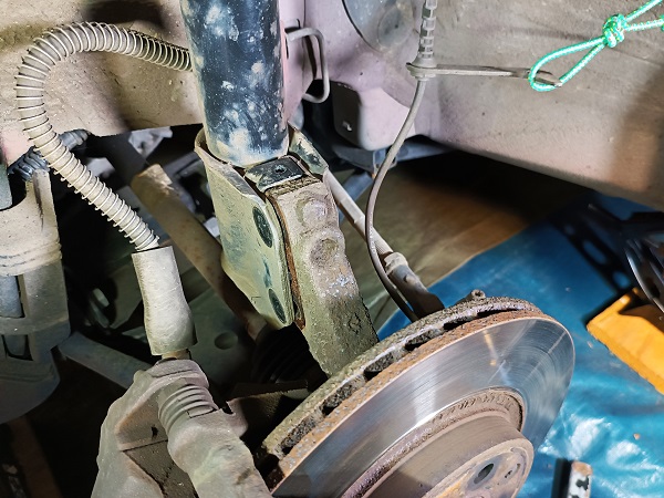
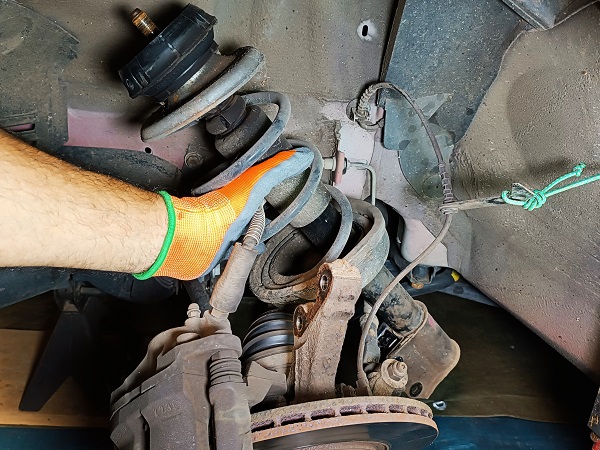
Detach the strut from the steering knuckle. Pull by hand.
Remove the strut.
Be careful not to damage the ABS harness or the brake hose when removing the strut.
When removing the strut, if the steering knuckle tilts outwards, it sometimes happens that the driveshaft comes off. In this case, replace the steering knuckle by oscillating the brake disc until the driveshaft clicks back into place.

Advertisement
Change the LH front shock absorber
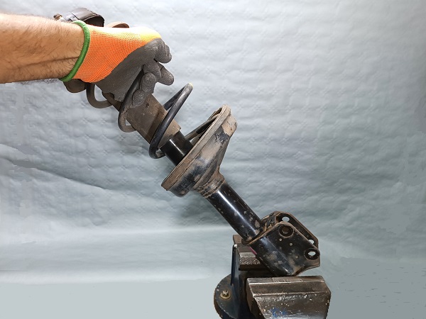
Op 16
Place the strut on a vice.
Removing the suspension spring is a very dangerous operation. As a safety precaution, it is strongly recommended to secure the strut in a vice before compressing the spring.
Op 17
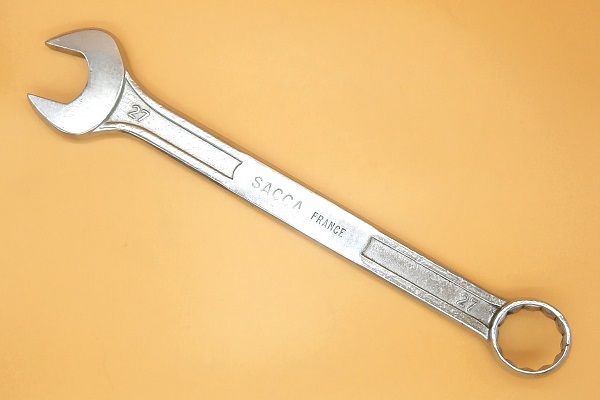
Unscrew the shock rod nut and bring it to the end of the rod. Use the 27 mm spanner and the 6 mm allen key.
Do not remove the shock rod nut for now. The spring could eject.
Positioning the nut at the end of the shock rod allows to slightly space the coils of the spring and this will facilitate the positioning of the coil spring compressor.
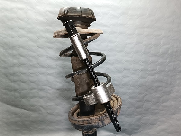
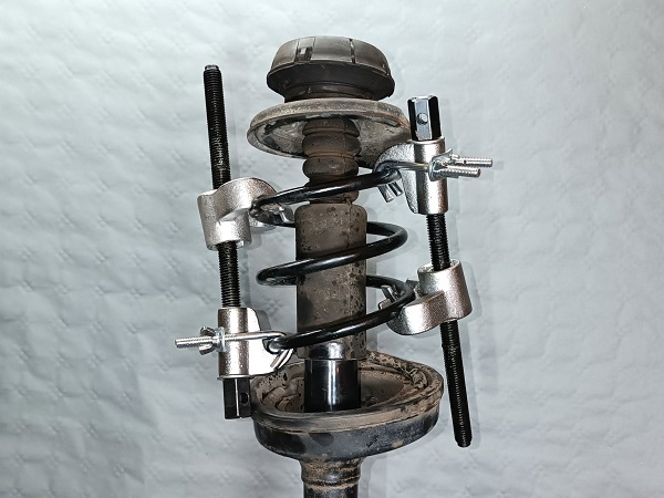
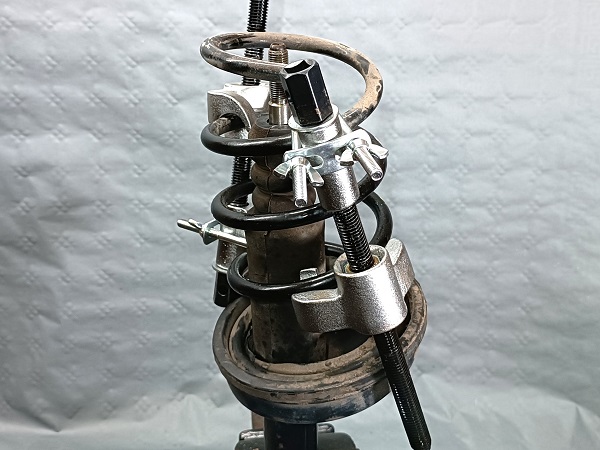
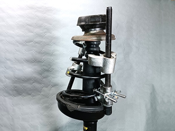
Op 18
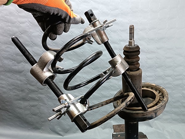
Fit the 2 elements of the coil spring compressor on the spring. Screw the threaded rods by hand for now.
Fit the 2 elements facing each other, taking the maximum number of coils of the spring.
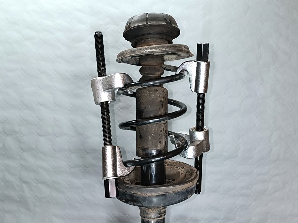
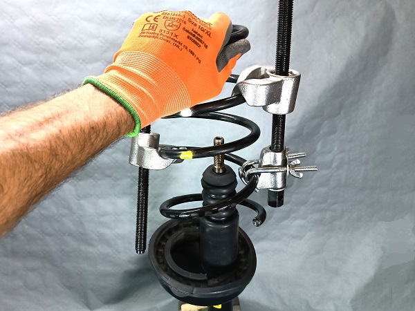
Op 19
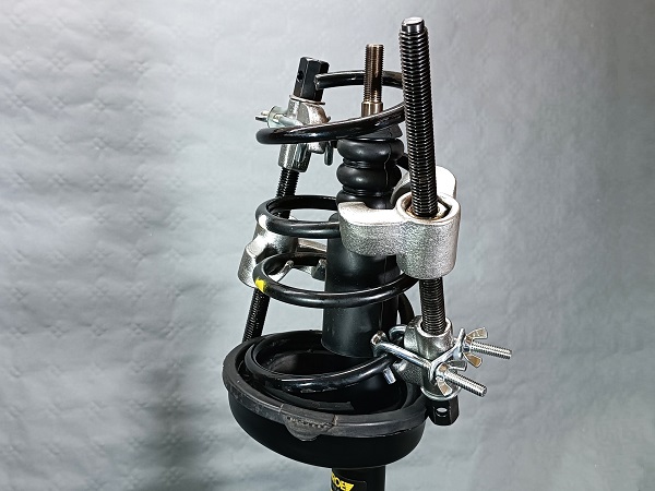
Fit the safety hooks on the upper heads of the coil spring compressor. Screw the wing nuts by hand.
Op 20
Tighten the 2 elements of the coil spring compressor gradually and alternately. Use the 1/2'' ratchet.
Tighten until the upper spring seat is released from the spring pressure.
Check that the spring is perfectly held by the coil spring compressor before proceeding to the next operation.


Op 21
Remove the shock rod nut. Use the 27 mm spanner and the 6 mm allen key.
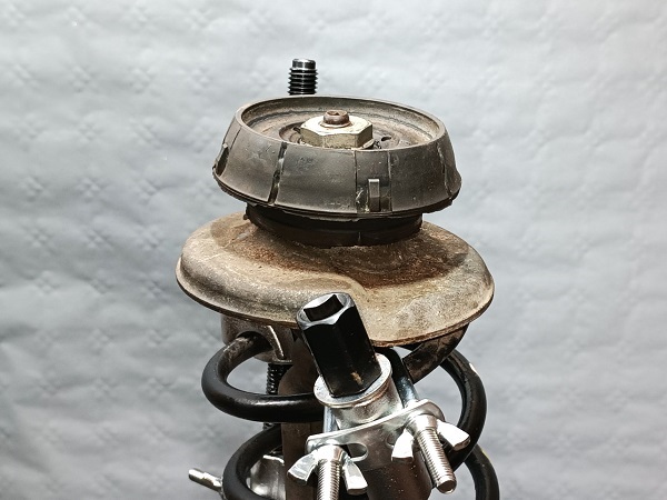

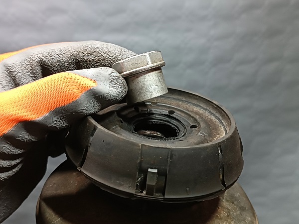
Op 22
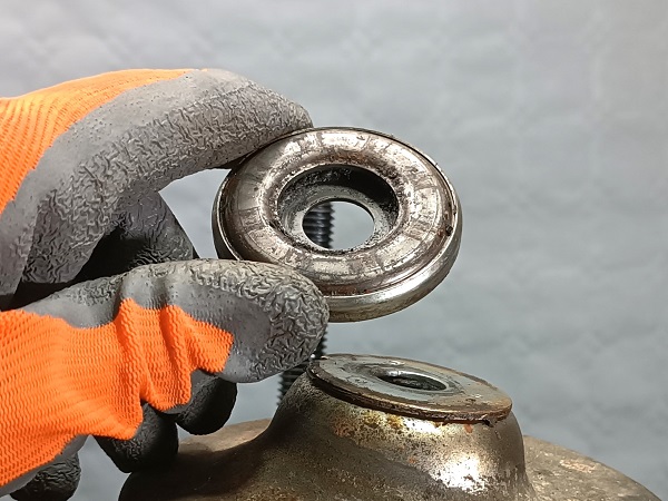
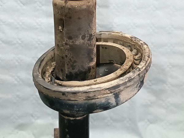
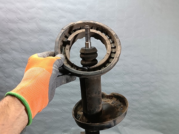
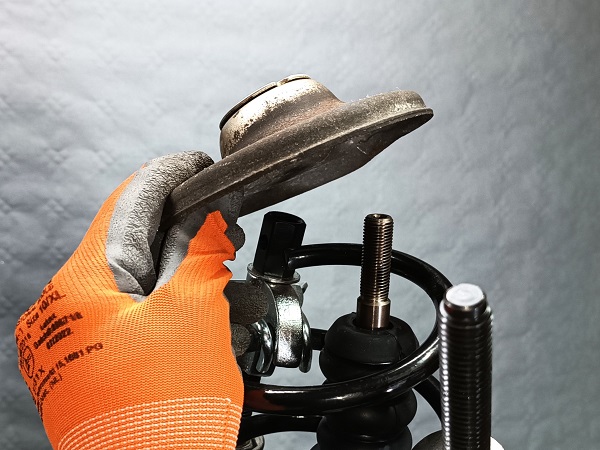
Remove the top strut mounting cushion (1st photo), the bearing (2nd photo) and the upper spring seat (3rd photo). Pull by hand.
Keep the upper spring seat because you will need it during reassembly.
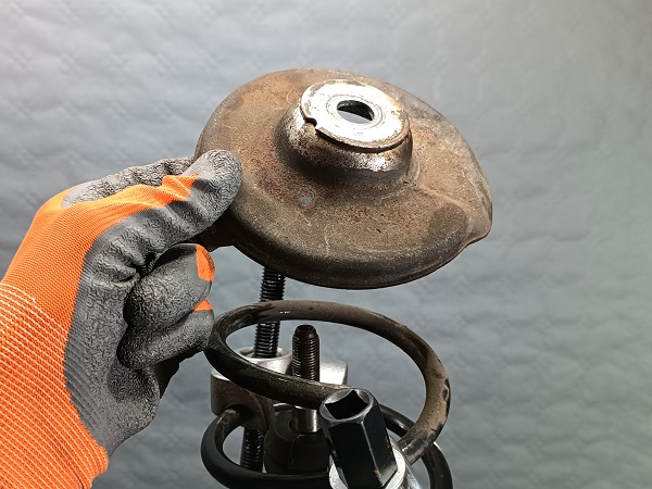
Op 23
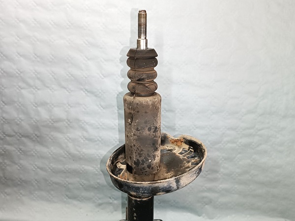
Remove the spring. Pull by hand.
Take great care when handling the spring as it is compressed by the coil spring compressor but is just waiting to relax.
Op 24
Remove the spring rubber cap. Pull by hand.
Keep the spring rubber cap because you will need it during reassembly.
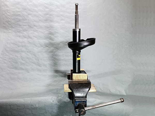
Op 25
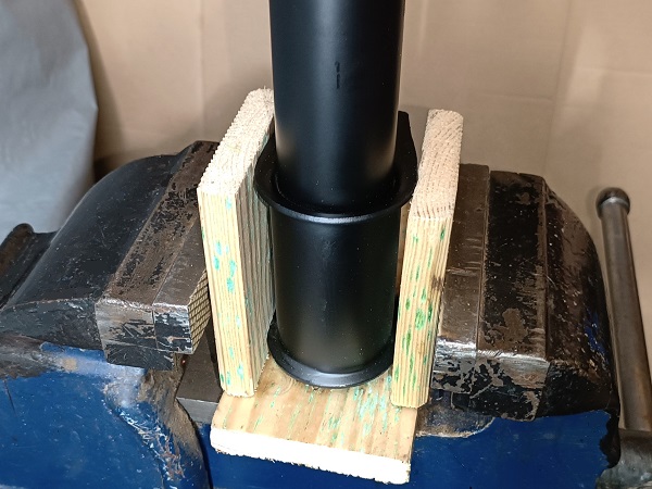
Fit the new shock absorber (8200367895) in a vertical position on a vice.
Insert soft jaws or pieces of wood (2nd photo) between the vice jaws and the shock absorber to avoid damaging it.
Op 26
Prime the new shock absorber :
•
Slide the shock rod 3 or 4 times over its entire stroke. Pull and push by hand.
Gas bubbles sometimes form in the oil inside new shock absorbers because they are frequently stored horizontally. It is therefore necessary to prime a shock absorber before mounting it on the vehicle. To do this, simply place it in a vertical position and slide the shock rod 3 or 4 times through its entire stroke.
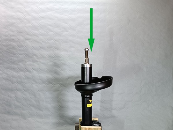
Op 27
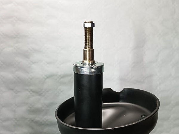
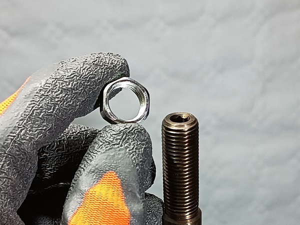
Remove the nut located on the shock rod. Unscrew by hand.
This nut is unnecessary because it is also included in the strut upper mount kit.
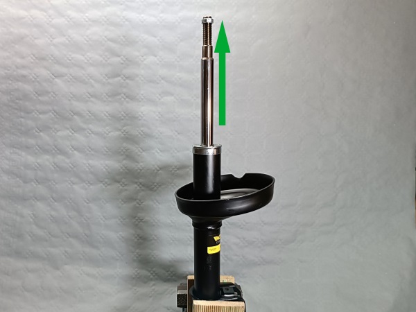
Op 28
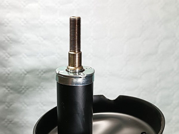
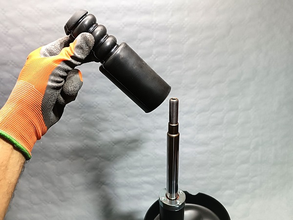
Slide the shock rod upwards. Pull by hand.
Fit the dust cap.

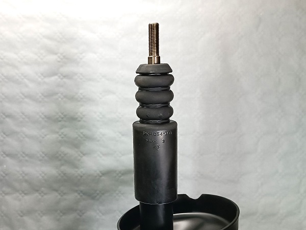
Op 29
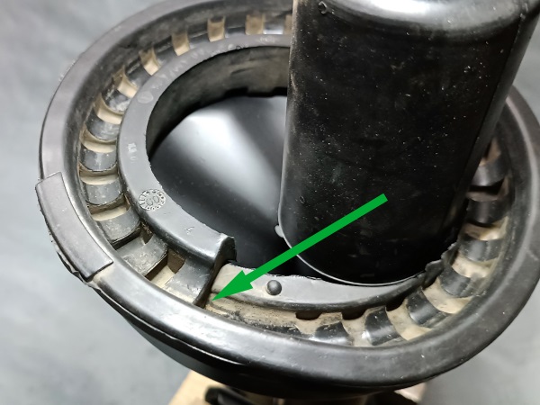
Fit the spring rubber cap on the shock absorber.
Engage the protuberance of the rubber in the notch of the shock absorber (2nd photo).
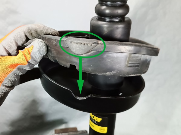

Op 30
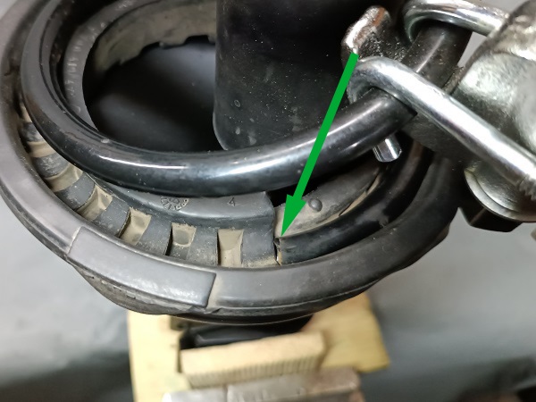
Fit the spring on the shock absorber.
Respect the correct positioning of the first coil of the spring on the spring rubber cap (2nd and 3rd photos).
Op 31
Fit the upper spring seat.
Respect the correct positioning of the last coil of the spring on the upper spring seat (2nd and 3rd photos).
Op 32
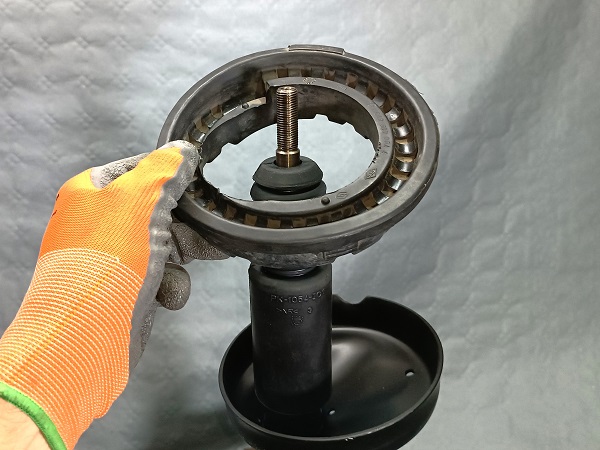
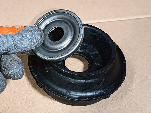
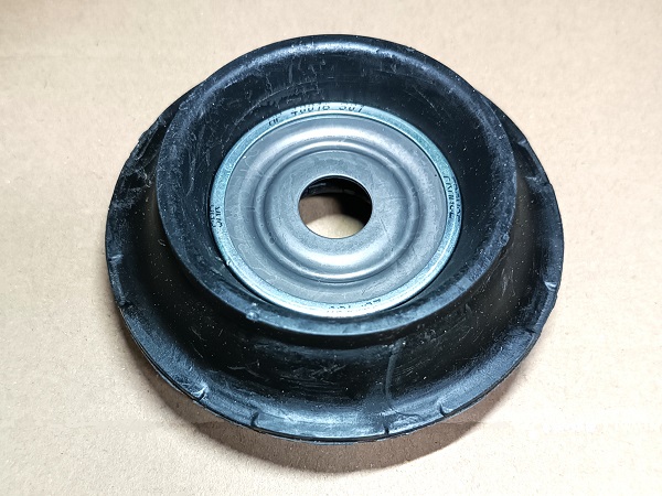
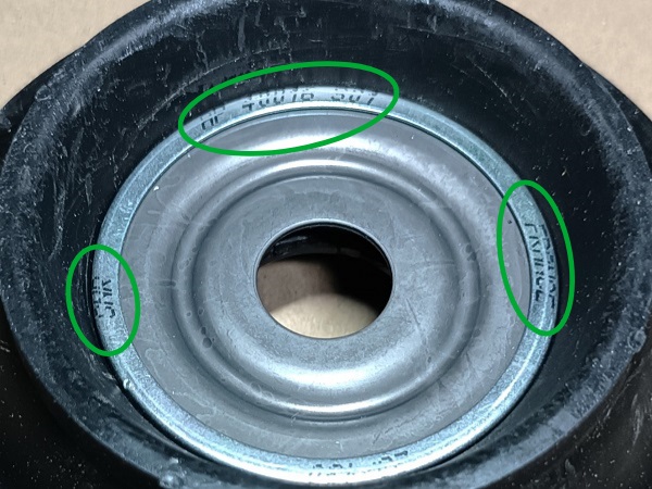
Fit the bearing in the top strut mounting cushion.
The bearing must be placed in the correct direction, otherwise it will hinder the operation of the steering. When the bearing is in the top strut mounting cushion, its marking must be visible (3rd photo).
Op 33
Fit the top strut mounting cushion and its bearing on the upper spring seat.
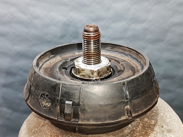
Op 34
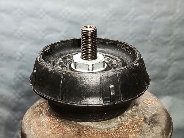
Fit the shock rod nut. Screw by hand for now.
Op 35
Remove the coil spring compressor. Use the 1/2'' ratchet.

Op 36
Screw the shock rod nut. Use the 27 mm spanner and the 6 mm allen key.
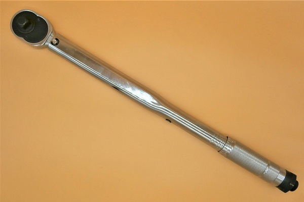
Tighten the nut to 62 Nm. Use the torque wrench and the long 27 mm socket.
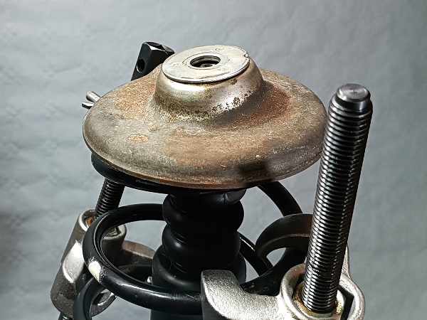
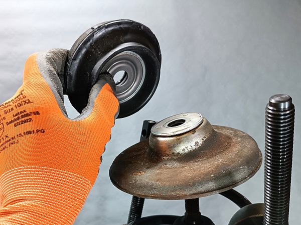
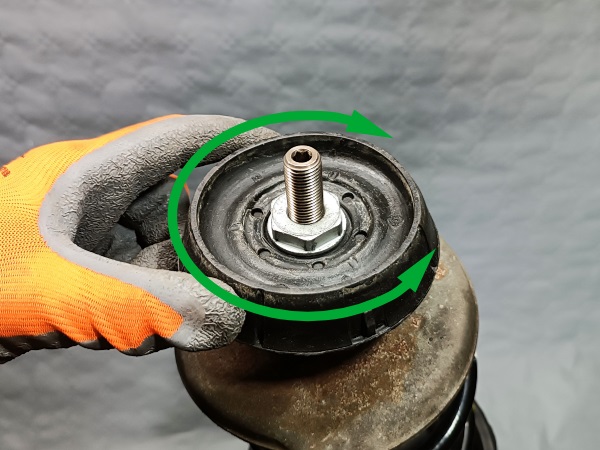
Op 37
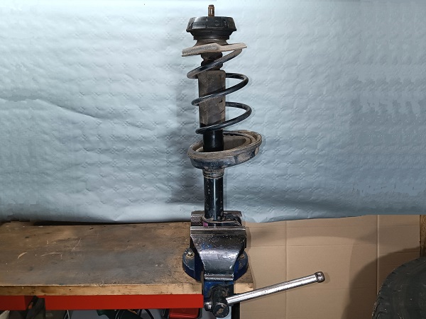
Check that the top strut mounting cushion rotates freely on its axis. Operate it by hand.
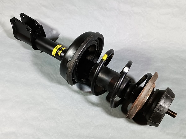
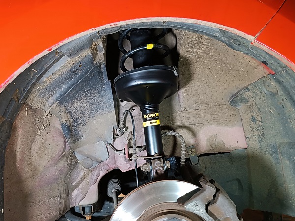
Admire this magnificent strut. It's like new. Bravo !
The top strut mounting cushion must be able to rotate freely so as not to hinder the operation of the steering.
Fit the LH front strut
Op 38
Fit the strut on the steering knuckle.

Op 39
Fit the 2 lower strut mounting bolts and their nuts. Use the socket and the 18 mm spanner.
Tighten the nuts to a torque of 105 Nm. Use the torque wrench.
The lower strut mounting nuts are nyloc nuts. Before each reassembly of such a nut, check that the nylon ring is in good condition and ensure locking. If in doubt, as a safety measure, fit a new nut.

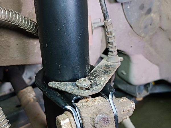
Op 40
Fit the ABS sensor harness support plate on the shock absorber.
Screw the ABS sensor harness mounting screw. Use the T30 torx key.
Op 41
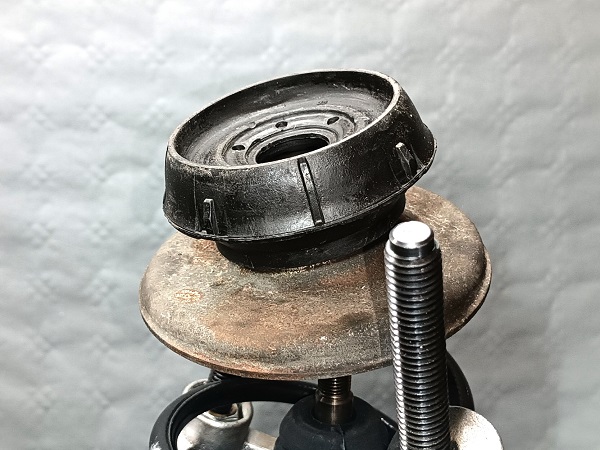
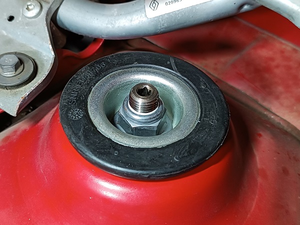
Fit the strut upper mount.
Op 42
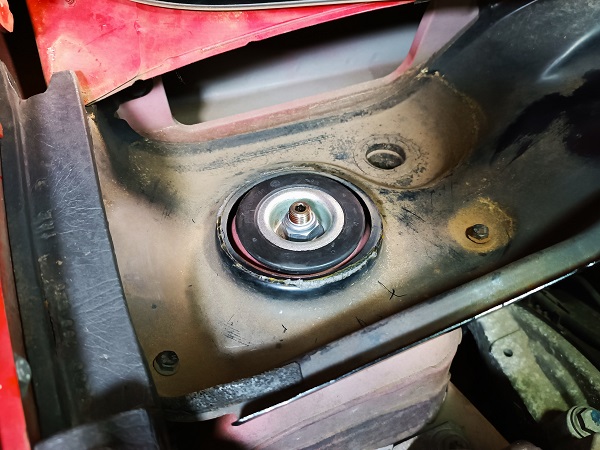
Fit the upper strut nut. Use the 21 mm go-through socket, the 22 mm spanner and the 6 mm allen key.
Tighten the nut to 21 Nm. Use the torque wrench and the 21 mm socket.
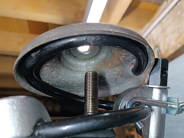
Once the strut upper mount is in position, you will be able to observe a clearance of a few millimeters between the strut upper mount and the body (5th photo). This is normal. This clearance is necessary for the proper functioning of the suspension (MacPherson type).

Op 43
Fit the wheel on the hub.
Screw the 4 bolts. Use the 17 mm socket.
Always start by screwing the bolts by hand. This will prevent you from stripping the threads.
No need to tighten too much. The final tightening will be done with the torque wrench when the wheel is on the ground.
Op 44
Lower the Twingo to the ground. Remove the jack stand and the jack.
Tighten the 4 bolts to a torque of 105 Nm. Use the torque wrench and the 17 mm socket.
Op 45
Fit the wheel trim. Fit it into the rim by pushing by hand.
Position the notch of the wheel trim at the valve (1st photo).
Advertisement
Change the RH front shock absorber
Op 46
Change the RH front shock absorber. Proceed in the same way as for the LH front shock absorber.
Final actions
Op 47
Fit the strut upper mount cover on the RH side :
•
Put some glue dots on the strut upper mount cover support plate. Use quick glue.
•
Fit the strut upper mount cover.
•
Let the glue dry.
Op 48
Fit the windscreen trim (➔ see the tutorial ''Windscreen trim removal'' Op 13 to 21).
Op 49
Fit the wiper arms (➔ see the tutorial ''Windscreen trim removal'' Op 22 to 24).
The End